
Exporting MFCD Displays
Exporting your displays / screens from inside the cockpit is a great way to more easily available information to you: you can forego the need to zoom in and look at the various screens (Multi Function Displays, Radar Warning Receivers) and instead have them on separate monitors always available to you!
Contents
Monitor Setup via .lua file
By far the most robust and future proof method of setting up display export(s) is to edit and use the MonitorSetup.lua file located in your DCS World install path. A monitor setup file holds the position for the various screens you want to export and view from the DCS client: these files use the .lua language which can appear daunting at first, but is in fact rather simple and convenient once you get to know it.
Editing program for .lua
Before we delve any further into opening and editing .lua files, let us first ensure that we have an appropriate (.lua) editor installed. Although the default Notepad shipped with most Windows installations may seem like a fitting program to use, Windows Notepad messes with the order and syntax ('spaces and lines/enters') within a file. This means that the file may become corrupted or unreadable in the eyes of the program using the .lua file if edited with the default Windows notepad (or equivalent program primarily designed for text editing).
As such we instead recommended 'Notepad++' (or any other program primarily designed for code editing, called IDE - Integrated Developer Environment) to use whenever you are editing a file written in programming language(s), as it does not have this flaw of editing the structure of the file. Notepad++ can be obtained here.
These MonitorSetup.lua files can be found (by default) in the DCS World Install location:
\DCS World (OpenBeta)\Config\MonitorSetup\

You will notice that there are a number of pre-made Monitor Setups available within this folder: we will go over opening and editing these files in a moment.
We can have any number of MonitorSetup.lua files stored in this folder, but we can only run one active MonitorSetup at a time. We can change this in 2 ways:
1) The first method is probably the most convenient and easiest to do, as it involves simply selecting the MonitorSetup within the DCS Settings menu. Open DCS, navigate to the options menu (the little cogwheel at the top) and from the list of available setups select the one you wish to use. Upon selecting the (hopefully) appropriate monitor setup file and clicking 'OK' the selected setup will become active, so be careful not to select the wrong setup file.
2) The second method is a little less convenient, but this method can also be used to restore back to any monitor setup without having to go through the DCS client. This becomes particularly helpful if you have selected the wrong monitor setup by accident and subsequently elements (such as the 'OK' button or the dropdown list) are being hidden off screen. We can change any DCS settings by going to:
\C:\Users\{Username}\Saved Games\DCS(.openbeta)\Config\options.lua
We can edit any setting in this file to alter the settings in DCS, but for altering the MonitorSetup file used we will want to change the "multiMonitorSetup" entry (either search this with CTRL+F or look it up under the "graphics" tab). You can change this to be any entry corresponding to a file within the \DCS\Config\MonitorSetup\ , but if in doubt the default is
["multiMonitorSetup"] = "1camera",
to restore it to the default DCS View.
MonitorSetup Overview
After installing the appropriate Notepad++ or other editor to edit our .lua files, we can now make a MonitorSetup file that corresponds to our own setup. To start, lets copy over an existing MonitorSetup file and rename it so that we have something to start with: let us use the LMFCD+Camera+RMFCD.lua file as an example.
A word of warning: if you fail to rename it to something unique (and instead leave it as LMFCD+Camera+RMFCD.lua(1) ) DCS will do weird stuff if you try to select this setup / profile. So please rename it, possibly to 'MyFirstSetup' or some such.

If we open this setup we can see that the screen is split up into 3 different screens, so-called 'viewports'. The most important viewport is our Center, which takes care of our main screen: we also have our left and right MFCD's exported onto the screen. In this setup the monitor is divided into 3 separate (horizontal) areas, which from left to right house the left MFCD, main screen and right MFCD respectively.
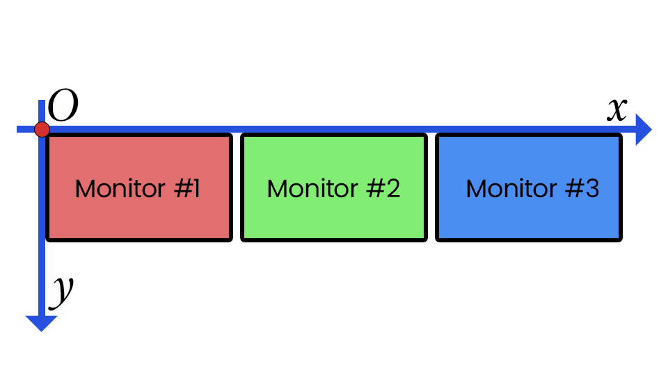
The various numbers listed are the coordinate locations in pixels, with X coordinates being drawn from left to right and Y coordinates from top to bottom. Thus (X,Y) = (0,0) is located at the top left of your screen, not the bottom left as you might expect.
Although we could choose to use the pixel values directly, we can also use some in-built commands (also present in the LMFCD+Camera+RMFCD.lua example) to get these values automatically for us. The command 'screen.width' gets the width of our screen, and 'screen.height' gets the total height of our screen: if you play on a resolution of 1920x1080, screen.width would return 1920 and screen.height would return 1080.
Our screen.aspect (also a command we can use, just not that useful) would then be 1.777777778, as it is 1920/1080 (= screen.width / screen.height). We can also use the appropriate mathematical expressions to allocate our 'viewports': in the .lua language you can use the plus +, minus -, divide /, and multiplication * operators.
MonitorSetup editing
The use of the .width, .height and .aspect commands allows for a nice dynamic scaling, as you do not have to calculate all the various pixel distances (widths and heights). It even allows for some (limited) interchangeability between different resolutions and screens.
If we (again) look at the LMFCD+Camera+RMFCD.lua MonitorSetup we find the following code, which sets up the 3 viewports according to the images shown.
   Center =
   {
   x = screen.width / 3;         -- Left side will start at this X point for the in-game resolution
   y = 0;                        -- Top side will start at this Y point for the in-game resolution
   width = screen.width / 3;     -- Width of the center viewport inside the game resolution
   height = screen.height;       -- Height of the center viewport inside the game resolution
   viewDx = 0;                   -- Horizontal default viewpoint direction
   viewDy = 0;                   -- Vertical default viewpoint direction
   aspect = screen.aspect / 3;   -- screen aspect: screen.width/screen.height by default
   }
   UIMainView = Viewports.Center
Similarly for the Left and Right MFCD (LEFT_MFCD and RIGHT_MFCD) viewports we find that these hold a start x and y point, as well as a width and height settings. These work similar to the examples listed above for the center viewport, except they do not have aspect or default viewpoint directions (as you can only view them headon, per their representation in the cockpit). Finally, the 'UIMainView = Viewports.Center' tells the .lua file where to place the Radio / JTAC UI in DCS; if not specified it will be placed all the way to the right (and thus may be obscured).

By altering the values we can alter the sizes and position of the various elements present in our DCS client. For example, a more reasonable MonitorSetup.lua with both MFCD's would be the one listed below. Note that the MFCD's (with height & width of 300 pixels) are overlapping the main screen: they get rendered over top because we specified them last. This can be both helpful and annoying, so plan ahead how you want to setup your Monitor.lua.
In a similar fashion we can have multiple instruments / screens from different aircraft overlap one another: as you cannot be in more than 1 aircraft simultaneously only the relevant instruments / screens from that aircraft will be drawn / rendered.
    _  = function(p) return p; end;
   name = _('MFCD');
   Description = 'More suitable?'
   Viewports =
   {
        Center =
        {
         x = 0;
         y = 0;
         width = screen.width;
         height = screen.height;
         viewDx = 0;
         viewDy = 0;
         aspect = screen.aspect;
        }
   }
   --
   LEFT_MFCD =
   {
    x = 0;
    y = screen.height - 300;
    width = 300;
    height = 300;
   }
   --
   RIGHT_MFCD =
   {
    x = screen.width - 300;
    y = screen.height - 300;
    width = 300;
    height = 300;
   }
   --
   UIMainView = Viewports.Center
Multiple displays
By default, DCS uses only the primary monitor with native resolution. Any resolution that exceeds the native resolution of the primary monitor, will result in output spanning multiple monitors. This can be a bit confusing at first but it's actually a very simple process. Drawing our Monitor layout and marking every key value is extremely helpful for visualization and calculation. Side by side same height monitors work just like having one ultrawide display, but mismatched monitors which are common with simpit setups will use the left monitor’s left edge and top monitor’s top edge would be the origin for the coordinates. Keep in mind that in both cases display output will only cover resolution entered in the settings, so we don't have to use all the monitors if we don't want to.
Same height displays

Mismatching displays


Don’t forget the values can be entered as mathematical expressions to save you from the calculations. Variables “screen.width” and “screen.height” are width and height of the entire resolution spanning the multiple displays and aren't to be confused with width and height of the single display.
Let's go through 3 different scenarios together with increasing complexity to better understand the coordinate system.
First scenario - 3 identical monitors
In this scenario we have three 1920x1080 monitors side by side, the left MFCD would be in the center of the left monitor, Center/main view would be in the middle and the right MFCD would be in the center of the third monitor. MFCDs should be preferably square so we would use the biggest possible size in this scenario which is 1080x1080.
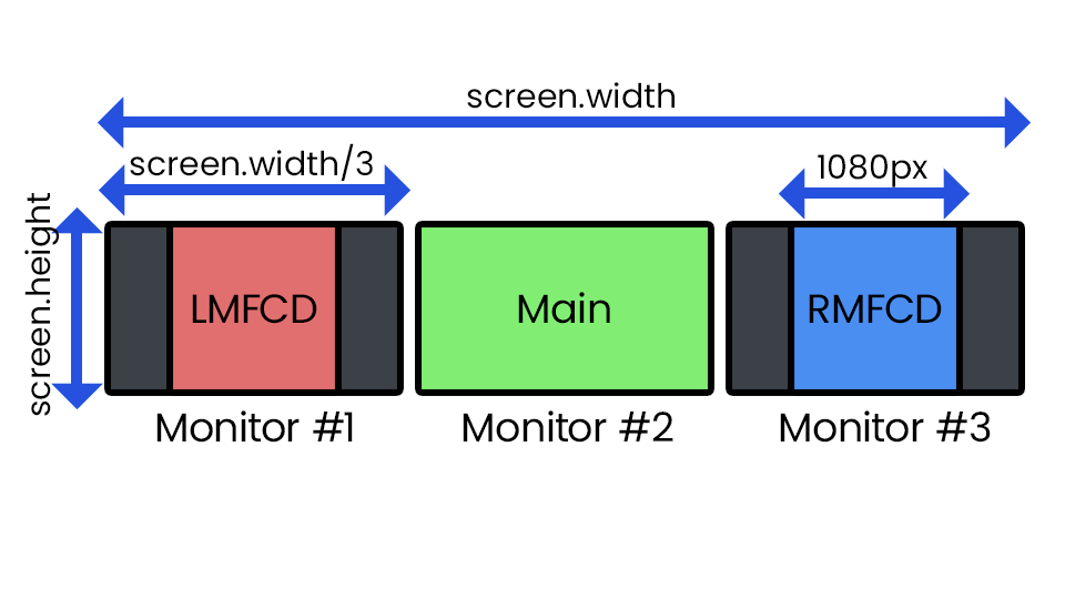
Triple 1080p same height displays

1. Let’s begin by copying the “LMFCD+Camera+RMFCD.lua” file and renaming it to “TripleMonitor.lua”.
2. Open the “TripleMonitor.lua” file and change the name and description as well. Use the same name as the file name to avoid confusion.
   name = _('TripleMonitor');
   Description = '5760*1080, 3 identical 1080p';
3. Then we start calculating the positions and the sizes of the different views.
Main/Center view is the easiest one, it starts from the right top corner of the first monitor into the second monitor, so we can use the expression
   x = screen.width / 3;
   y = 0;
The width and height would be “screen.width / 3” and “screen.height”, but we can also simply use
   width = 1920;
   height = 1080;
4. For the purpose of centering the left MFCD horizontally it would have the same distance to the right and left edge of the left display. This equates to
x = ((screen.width / 3) - 1080) / 2;
and y would simply be 0. 5. The right MFCD has similar properties but it's on the third monitor, so we can simply copy left MFCD values and add 2 monitor widths to it.
   x = ((screen.width / 3) - 1080) / 2 + 3840;
   y = 0;
At this point we should have the following code which is complete and functional:
   _  = function(p) return p; end;
   name = _('TripleMonitor');
   Description = '5760*1080, 3 identical 1080p';
   Viewports =
   {
     Center =
     {
       x = screen.width / 3;
       y = 0;
       width = 1920;
       height = 1080;
       viewDx = 0;
       viewDy = 0;
       aspect = 16/9;
     }
   }
   LEFT_MFCD =
   {
     x = ((screen.width / 3) - 1080) / 2;
     y = 0;
     width = 1080;
     height = 1080;
   }
   RIGHT_MFCD =
   {
     x = ((screen.width / 3) - 1080) / 2 + 3840;
     y = 0;
     width = 1080;
     height = 1080;
   }
   UIMainView = Viewports.Center
   GU_MAIN_VIEWPORT = Viewports.Center
We can also just use number values to avoid mistakes and syntax errors.
   _  = function(p) return p; end;
   name = _('TripleMonitor');
   Description = '5760*1080, 3 identical 1080p';
   Viewports =
   {
     Center =
     {
       x = 1920;
       y = 0;
       width = 1920;
       height = 1080;
       viewDx = 0;
       viewDy = 0;
       aspect = 16/9;
     }
   }
   LEFT_MFCD =
   {
     x = 420;
     y = 0;
     width = 1080;
     height = 1080;
   }
   RIGHT_MFCD =
   {
     x = 4260;
     y = 0;
     width = 1080;
     height = 1080;
   }
   UIMainView = Viewports.Center
   GU_MAIN_VIEWPORT = Viewports.Center
We might also prefer both MFCDs being edge to edge to our main view rather than being center of the screen. In that case coordinates would change accordingly.
   LEFT_MFCD =
   {
     x = 840;
     y = 0;
     width = 1080;
     height = 1080;
   }
   RIGHT_MFCD =
   {
     x = 3840;
     y = 0;
     width = 1080;
     height = 1080;
   }
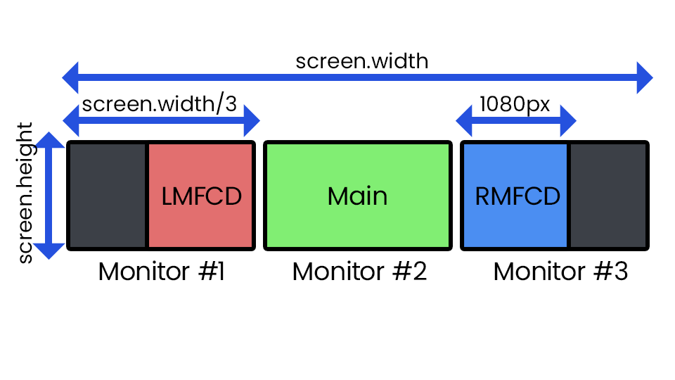
Triple 1080p alternative

Now we should save the file, and select this profile in DCS settings and choose resolution of 5760x1080. After DCS restarts, we would realize both side displays are blacked out, but they will be populated with MFCDs once we are in an aircraft.
Second scenario - 2 mismatched monitors
In this scenario we have a 1920x1080 monitor on the left and 2560x1440 monitor with their bottom edge aligned rather than top edges. We want both LMFCD and RMFCD on the left monitor side by side and main view on the right monitor. Therefore both MFCDs have sides that are 960 pixels.
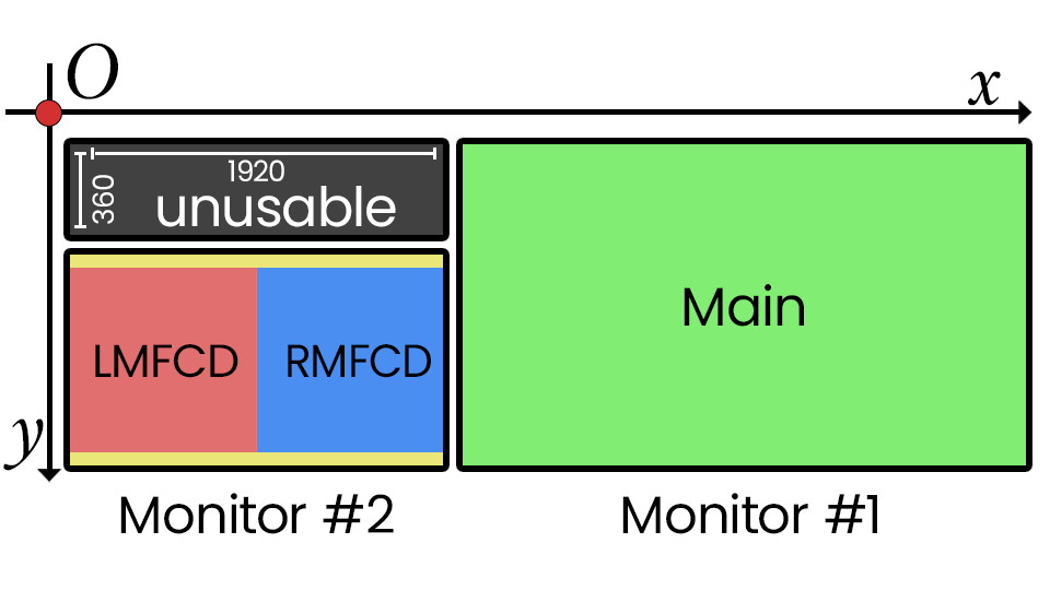
2 mismatched monitors

Notice how the origin of the coordinates aren't on either monitor and some unusable and inaccessible window. This can cause DCS to render portions in this inaccessible window and prevent us from accessing options to revert to default settings. If that happens navigate to
\C:\Users\{Username}\Saved Games\DCS(.openbeta)\Config\options.lua
to revert to default settings as explained above.
1. As the copying and renaming steps are the same as above. So let's copy “LMFCD+Camera+RMFCD.lua” again and name our file “2Monitor.lua” and update the name and description.
   name = _('2Monitor');
   Description = '4480*1440, 1080p left, 1440p right, bottom aligned';
2. The main view is on the second monitor, x value is predictably 1920. y value is 0 as it has no gap on the top.
   x = 1920;
   y = 1080;
3. The left edge of the LMFCD starts with left edge of the display therefore x = 0.
The top edge however, starts 60px from the top edge of the display which is already 360px below the origin. Therefore we have a y value of 420.
   x = 0;
   y = 420;
   width = 960;
   height = 960;
4. RMFCD has the same vertical position but should be to the right of the LMFCD. We can simply copy the values and add 960px to the x value.
   x = 960;
   y = 420;
   width = 960;
   height = 960;
Same as before, go to DCS options and choose the "2Monitor" mode and the resolution of 4480x1440, save and reboot.
Just like that, we have mismatched monitors working perfectly.
Third scenario - 4 mismatched monitors
This scenario has one 4K(3840x2160) monitor with 2 custom 1024x960 displays attached to the bottom, and a 1080x1920(vertically oriented) display. The primary 4K display would be our main view and 2 custom displays for MFCDs, whilst the right display is unused and reserved for flight manual, mission briefing or livestream interactions.
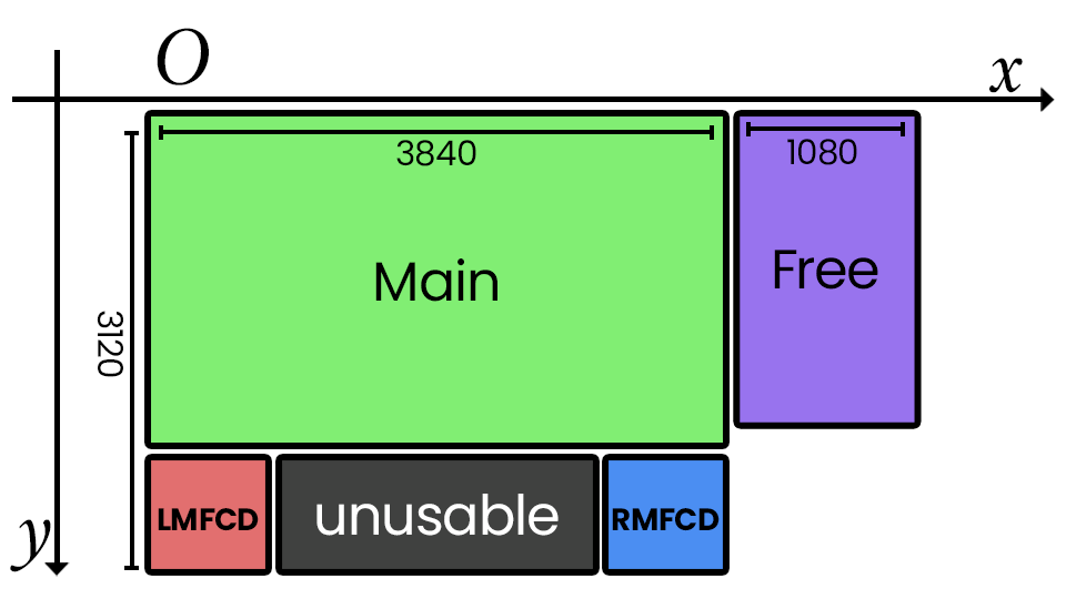
4 mismatched monitors

1. Same as above - copying file, file rename, updating profile name and descriptions.
   name = _('4Monitor');
   Description = '4 monitor setup';
2. Main view should be easy.
   Center =
   {
     x = 0;
     y = 0;
     width = 3840;
     height = 2160;
     viewDx = 0;
     viewDy = 0;
     aspect = 16/9;
   }
3. Let's assume we want the MFCDs at the top edge of the custom displays since they're not perfectly square. LMFCD is at the bottom-left edge of the main view, RMFCD is at the bottom right edge of the main view and both are 960x960 pixels.
   LEFT_MFCD =
   {
     x = 0;
     y = 2160;
     width = 960;
     height = 960;
   }
   RIGHT_MFCD =
   {
     x = 3840 - 960;
     y = 2160;
     width = 960;
     height = 960;
   }
4. Now let's save, launch DCS and go to options. Notice after selecting the “4MonitorCustom” profile, in resolution selections, there is only 4920x3120 option after the native resolution, which upon selection and reboot of DCS would blackout the right display despite not rendering anything on it. to avoid this, we would manually enter our own calculated resolution 3840x3120, save and reboot.
Now everything should work as planned.
Note that only the displays on the right and/or bottom side can be unpopulated at the time of this writing due to how the coordination system works.
If there is an aircraft that has third or more MFCD outputs, just add the following code block after RIGHT_MFCD with the same logic and syntax. Module handbook or flight manual of that aircraft should provide more information.
   EXAMPLE_THIRD_MODULE =
   {
     x = {horizontalPos};
     y = {verticalPos};
     width = {w};
     height = {h};
   }
Viewports
Here are all the varying items you can viewport by default: please reference the resources links on how to export more items to viewports. Recall that only instruments / screens from the current aircraft will be drawn rendered, so you can stack multiple instruments / screens from different aircraft in one location.
Resources
How to add Viewports to any instrument
Dummies Guide for the MonitorSetup.lua by FrankP (Nice images!)
Adding custom resolution templates to DCS
Has exporting to a second or third monitor messed up your kneeboard?
Ultra MFCD

It works with multi-monitor setups, works with touchscreens, visit the page in the link above to see all of it's available features.