Difference between revisions of "JF-17"
m (→Useful links) |
m (→Weapons List) |
||
| (29 intermediate revisions by 4 users not shown) | |||
| Line 1: | Line 1: | ||
| − | + | {{#widget:AdSense | |
|name=Hoggitwiki header | |name=Hoggitwiki header | ||
|client=ca-pub-6997190595986605 | |client=ca-pub-6997190595986605 | ||
| Line 5: | Line 5: | ||
|width = 728px | |width = 728px | ||
|height = 90px | |height = 90px | ||
| − | }} | + | }} |
{{ModuleInfo | {{ModuleInfo | ||
|modulename=JF-17 | |modulename=JF-17 | ||
| − | |modulethumb= | + | |modulethumb=Jeff Wiki 1.png |
|guidelink=https://www.mudspike.com/chucks-guides-dcs-jf-17-thunder/ | |guidelink=https://www.mudspike.com/chucks-guides-dcs-jf-17-thunder/ | ||
|storelink=https://www.digitalcombatsimulator.com/en/shop/modules/thunder/ | |storelink=https://www.digitalcombatsimulator.com/en/shop/modules/thunder/ | ||
|trailerlink=https://www.youtube.com/watch?v=OeHtlV-Z0fo | |trailerlink=https://www.youtube.com/watch?v=OeHtlV-Z0fo | ||
}} | }} | ||
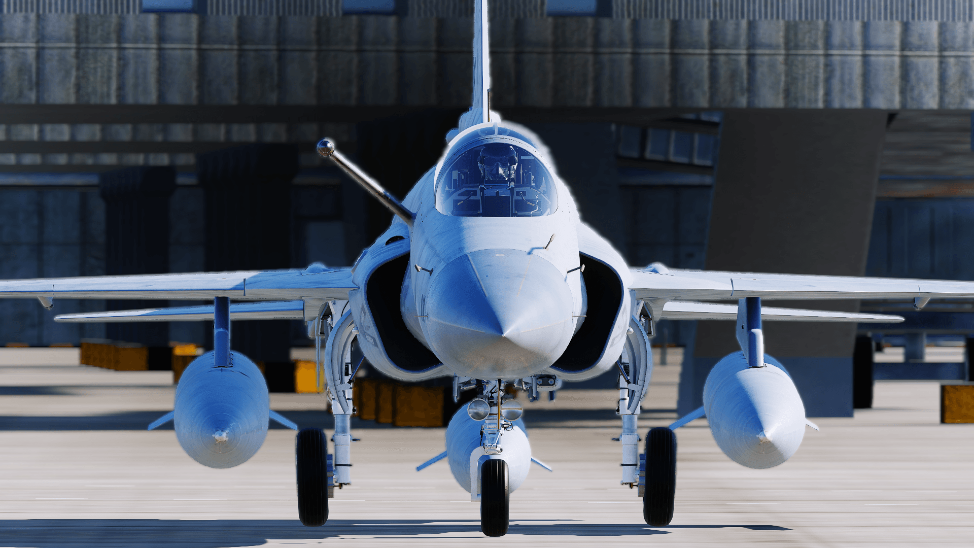
| + | The JF-17 is a low-cost, low-maintenance, lightweight, single-engine, fourth-generation multi-role combat aircraft designed, developed, and produced jointly by the Pakistan Aeronautical Complex (PAC) and the Chengdu Aircraft Corporation (CAC) of China. | ||
| + | Designed and built to replace the Pakistani Air Force’s 2nd and 3rd generation fighters such as the Mirage III, A-5, and F-7. | ||
| + | The JF-17 entered service with the PAF in 2007, in PAF service it has conducted multiple anti-terrorist operations on the Pakistan-Afghanistan border. | ||
| + | The JF-17 has also entered service with the Myanmar Airforce with an order of 16 airframes (of which 7 have been delivered so far). | ||
| + | |||
| + | Capable of carrying multiple types of weapons such as the GPS guided LS-6 and GB-6 and the BVRAAM SD-10 missile it is a very capable airframe. It is also the newest aircraft released as a module in DCS, with its first flight in 2003, only 17 years ago. The version we have in DCS is primarily a Block I with some Block II features: the removable aerial refueling probe being one of the most notable examples of features from the Block II. | ||
| + | |||
__TOC__ | __TOC__ | ||
<center>{{#widget:AdSense | <center>{{#widget:AdSense | ||
| Line 22: | Line 29: | ||
|height = 90px | |height = 90px | ||
}}</center> | }}</center> | ||
| + | =Weapons List= | ||
| + | ---- | ||
| + | The JF-17 is capable of carrying: | ||
| + | *Mk-82 series 500lbs unguided bomb | ||
| + | *Mk-83 series 1,000lbs unguided bomb | ||
| + | *Mk-84 series 2,000lbs unguided bomb | ||
| + | *Mk-20 cluster bombs | ||
| + | *Hydra 70 2.75 inch rockets | ||
| + | *GSH-23 23mm cannon (A/A & A/G) | ||
| + | *PL-5EII infrared-guided air-to-air missile | ||
| + | *SD-10 active radar homing air-to-air missile | ||
| + | *C-701IR infrared-guided air-to-ground missile | ||
| + | *C-701T television-guided air-to-ground missile | ||
| + | *GBU-10 Paveway II 2,000lbs laser-guided bomb | ||
| + | *GBU-12 Paveway II 500lbs laser-guided bomb | ||
| + | *GBU-16 Paveway II 1,000lbs laser-guided bomb | ||
| + | *LD-10 anti-radiation missile | ||
| + | *GB-6-HE GPS-guided glide cluster bomb | ||
| + | *GB-6-SFW GPS-guided glide SFW-cluster bomb | ||
| + | *GB-6 GPS-guided glide bomb | ||
| + | *LS-6 GPS-guided glide bomb | ||
| + | *CM-802AKG air-to-ground cruise missile | ||
| + | *C-802 anti-ship missile | ||
| + | *BRM-1 Laser-Guided Rockets | ||
| + | *Type-200A Unguided Anti-Runway Bomb | ||
| + | |||
| + | =Hotas= | ||
| + | The JF-17 has a modern Hands On Throttle And Stick system (HOTAS) which means that most controls the pilot will need in flight will be kept on his HOTAS, thus negating the need to move focus around the cockpit. | ||
| + | The Switches on the HOTAS are either named T for Throttle or S for stick. | ||
| + | The list of controls is: | ||
| + | |||
| + | On the throttle: | ||
| + | *'''T1:''' selects Master Mode | ||
| + | **Up: AA master mode | ||
| + | **Middle: NAV master mode | ||
| + | **Down: AG master mode | ||
| + | *'''T2''': Controls Countermeasures | ||
| + | **Forward: Engages SPJ (Self-Protection Jammer) | ||
| + | **Push: Cages PL-5 seeker | ||
| + | **Backwards: Dispenses Countermeasures | ||
| + | *'''T3''': engages/disengages the Speedbreak | ||
| + | **Forwards: Speed Brake on | ||
| + | **Push: Speed brake on/off | ||
| + | **Backwards: Speed Brake of | ||
| + | *'''T4''': Radio PTT and IFF interrogation: | ||
| + | **Forward: Comm 1 PTT | ||
| + | **Push: IFF interrogation start/stop | ||
| + | **Backward: Comm 2 PTT | ||
| + | *'''T5''': TDC acts as a mouse to slew the various sensors. | ||
| + | *'''T6''': antenna elevation: while in: | ||
| + | **Targeting pod: controls zoom | ||
| + | **A/A radar controls scan elevation | ||
| + | |||
| + | On the Stick: | ||
| + | *'''S1:''' Sensor Selection (SS) selects the SOI | ||
| + | **Forward: Selects ACM mode | ||
| + | **Backward: Cycle HUD/Center MFD as SOI | ||
| + | **Right: Select Right MFD as SOI | ||
| + | **Left: Select Left MFD as SOI | ||
| + | *'''S2:''' Sensor Control: | ||
| + | **Forward: Increases Display distance and enters Boresight mode when in DGFT master mode | ||
| + | **Backward: decreases display distance and enters vertical scan mode when in DGFT master mode | ||
| + | **Right: Change Azimuth Scan range and enters Heads-Up display area when in DGFT master mode | ||
| + | **Left: in A/A: | ||
| + | ***In TWS,RWS or VS mode: cycles between them | ||
| + | ***SAM mode: Cycles between SAM and NAM sub-modes | ||
| + | *'''S3:''' Weapon release | ||
| + | *'''S4:''' Gun trigger | ||
| + | *'''S5:''' Missile step / NWS | ||
| + | *'''S6:''' Trim | ||
| + | *'''S7:''' Autopilot disengage | ||
| + | *'''S8:''' cycles between weapon profiles | ||
| + | =Cockpit and avionics= | ||
| + | |||
| + | ==Sensor assignment== | ||
| + | to select the sensor which you want the TDC to slew press S1 towards the MFD where the sensor is displayed (so if Targeting pod is on the left S1 left will set Targeting pod as SOI). S1 backwards also cycles between HUD and MFD as SOI. A star should appear on the bottom-center of the selected screen to indicate that it is currently SOI. | ||
| + | |||
| + | ==INS== | ||
| + | The JF-17 has an Inertial Navigation System that provides navigational data to the aircraft, it’s systems, and it’s weapons. A Inertial Navigation System works by measuring the rotation, velocity and direction of the aircraft by dead reckoning from it’s initial Position. An INS system is liable to drift, especially with a FAST alignment, however there are multiple ways to correct this drift, the JF-17 corrects the drift by using a Hybrid INS-GPS system, the HNS (Hybrid Navigation System). There are two different modes of alignment, fast alignment and GC alignment, the fast alignment is meant for situations in which GPS is available. Alignment in this mode takes 40 seconds. GC mode does a full alignment and is thus more impervious to drift, it is done in situations where GPS is not available. (or when using GPS guided munitions such as the LS-6 or GB-6). GC alignment takes 3:40 minutes to align. | ||
| + | ===Alignment Process=== | ||
| + | ====Fast==== | ||
| + | *1) On the DEST page on the UFCP enter the coordinates and altitude provided in the kneeboard in WPT 0 | ||
| + | *2) Flip the INS knob to FAST | ||
| + | *3) On the INS page on the MFD enter heading by: | ||
| + | *4) pressing on the arrow | ||
| + | *5) enter the Heading provided in the kneeboard | ||
| + | *6) Wait for remaining time to reach 0:00 and ALIGN on the hud, or FAST on the MFD to start flashing | ||
| + | *7) Flip INS knob to NAV | ||
| + | Note: if you flip the knob directly to NAV instead of to FAST it will proceed with a FAST alignment but will automatically flip to NAV when alignment is complete. | ||
| + | ====GC (Full)==== | ||
| + | *1) On the DEST page on the UFCP enter the coordinates and altitude provided in the kneeboard in WPT 0 | ||
| + | *2) Flip the INS knob to GC | ||
| + | *3) Wait for remaining time to reach 0:00 and ALIGN on the hud, or FAST on the MFD to start flashing | ||
| + | *4) Flip INS knob to NAV | ||
| + | |||
| + | |||
| + | ==Cockpit== | ||
| + | The Jf-17’s glass cockpit is made up of 3 Multi-Color MFDs, a UFC, a HUD and various switches and knobs required for the operation of the aircraft. | ||
| + | |||
| + | ===AAP=== | ||
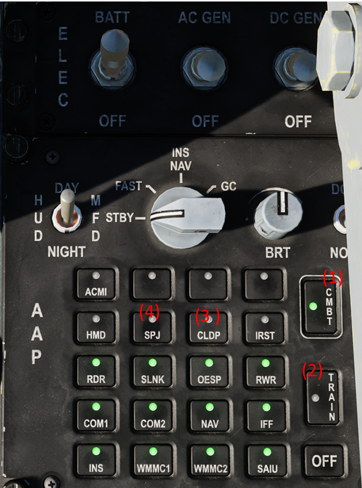
| + | The AAP (Avionics Activation Panel) houses all the buttons that powers on the various avionics of the JF-17 via it’s labelled buttons; Green means powered on. Pressing ‘’’CMBT’’’(1) will power on all Avionics required for an A2A mission and ‘’’TRAIN’’’’(2) will turn on all avionics required for a basic training mission (no weapons employment). Each avionic can also be powered on/off individually by clicking on the corresponding button. An important thing to remember is that the TPOD and SPJ are not powered on automatically. To turn on the TPOD the ‘’’CLDP’’’(3) button must be clicked. And ‘’’SPJ’’’ to power on the jammer pod(4). | ||
| + | Note: HMD and the IRST buttons are currently not functional. | ||
| + | [[File:AAP.png|400px|thumb|center|AAP|]] | ||
| + | |||
| + | ===MFCDs=== | ||
| + | |||
| + | The JF-17 has 3 large format Multi Function Colour Displays as its primary instrumentation for flight in addition to the HUD and the UFCP. Each MFCD is fully capable of displaying full colour imagery and is divided into two sections, a Primary Display along the top and a Secondary Display underneath, sectioned off by a white dividing line. The MFCDs are controlled using a series 26 On Screen Buttons, 8 along the left and right and 5 along the top and bottom. Control of the image over the entire MFCD is accomplished by 3 rocker switches in the top right, bottom right and bottom left corners, controlling Symbology Brightness, Image Contrast and Image Brightness respectively, and power is controlled through a 2 position rotational switch in the top left corner, initialised to on by default. | ||
| + | |||
| + | Primary Display Pages are accessed either through the Main Menu Page, through the Data Submenu for Data Pages, or using the quick access OSBs at the bottom of the MFCDs. The default displays are assigned based on the current selected Master Mode. Primary Display Pages are controlled either through the HOTAS or by using the 5 Top OSBs and the first 5 Left and Right OSBs. The Centre Bottom OSB is always used to return the MFCD Primary Display to the Main Menu. | ||
| + | |||
| + | Secondary Display Pages are controlled using the lower 3 Left and Right OSBs and accessed through a Secondary Main Menu accessed through the Bottom Right OSB labelled RTN. | ||
| + | |||
| + | Quick access buttons are assigned as such: | ||
| + | *Left MFCD: CMBT/SMS, unless SMS selected in which case CMBT/JETT | ||
| + | *Centre MFCD: RDR/(Blank) | ||
| + | *Right MFCD: HSD/CLNK | ||
| + | |||
| + | And pages will default to: | ||
| + | *Left MFCD: SMS unless in NAV Master Mode in which case EFIS | ||
| + | *Centre MFCD: RDR | ||
| + | *Right MFCD: HSD | ||
| + | |||
| + | ===UFCP=== | ||
| + | The UFCP (Up Front Control Panel) is similar in function to the hornet and Harrier’s UFCs | ||
| + | On the left is a standard numerical keypad which are also used to enter different UFCP Functions (pages, Menus) when not entering data. On the center of the screen are 4 green lines surrounded by arrows on both sides by arrows (the UFCP Data Field and Data Field select buttons), you click on these arrows to edit the data you want to input on the data field. On the left of the Datafield are The UFCP Priority Functions, these enter various functions on the UFCP. under the UFCP between the HUD brightness knob and the HUD standby reticle knob is a dobber switch that can be used to quickly increase the selected value, for example if you are on WPT 1 and wish to switch to 2, instead of entering 02 on the Keypad you click + on the dobber switch, and it will increment upwards towards WPT2. | ||
| + | |||
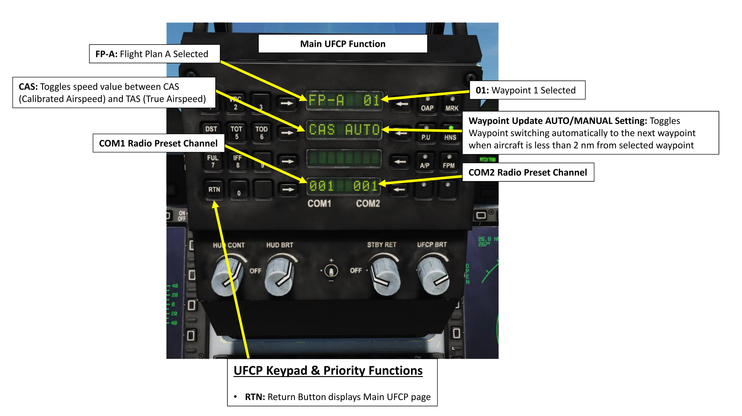
| + | The “Main Menu” of the UFCP is clicked by pressing RTN on the keypad, this will return you to the main page no matter what display you are on. (unless you are entering data in which case it will cancel it). The Main page consists of the current selected Flight plan at the top, in our case FP-A, along with the current selected waypoint on the right of the FP. right under that there is the switch between CAS and TAS, (Calibrated Air Speed and True Airspeed) and to the right of that is the AUTO/MAN switch which toggles the automatic sequencing of Waypoints. Then at the very buttom are the two radios, Comm 1 and Comm 2 displaying the current preset Frequency. | ||
| + | [[File:JF-17Mainpage.png|600px|thumb|center|Main Function of the UFCP (original Image from Chuck's guide, used with permission from author)]] | ||
| + | |||
| + | Important UFCP functions are: | ||
| + | ====DST==== | ||
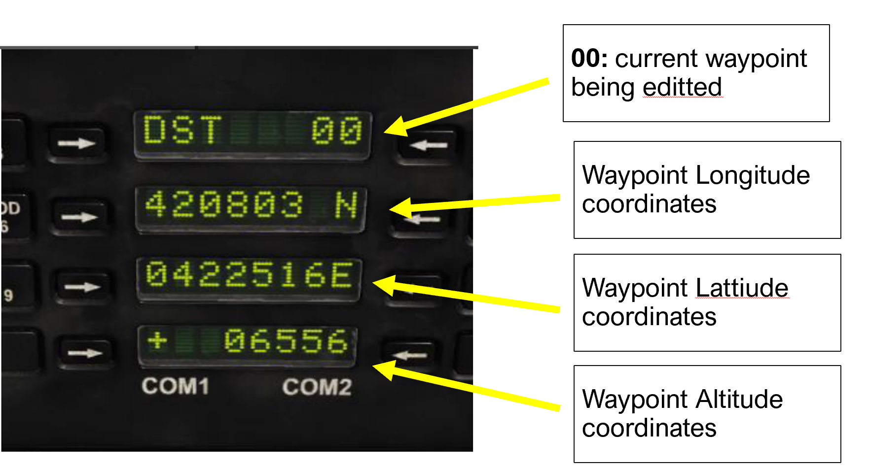
| + | DST (Destination) is for the entering and editing of waypoints, top entry line has the current waypoint being edited on the right, and below that are the Coordinates in DD*MM’SS.S and at the very bottom is the altitude of the Waypoint. | ||
| + | [[File:JFDST.png|400px|thumb|center|DEST page of the UFCP]] | ||
| + | ====Fuel==== | ||
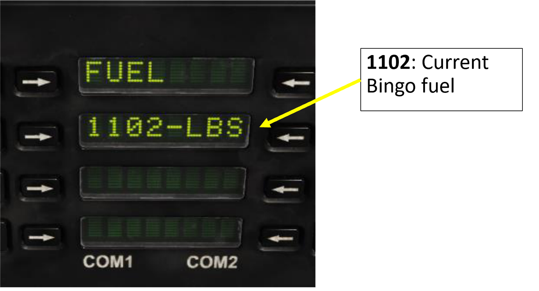
| + | Sets the current Bingo fuel. When this the fuel readout reaches this amount a warning will be given. If Waypoint mode is set to AUTO the EMMC will be set to BINGO and waypoint 50 (Home Plate) will be selected. | ||
| + | [[File:Fuel Page.png|400px|thumb|center|Fuel page of the UFCP|]] | ||
| + | |||
| + | ====IFF==== | ||
| + | WIP | ||
| + | ====MRK==== | ||
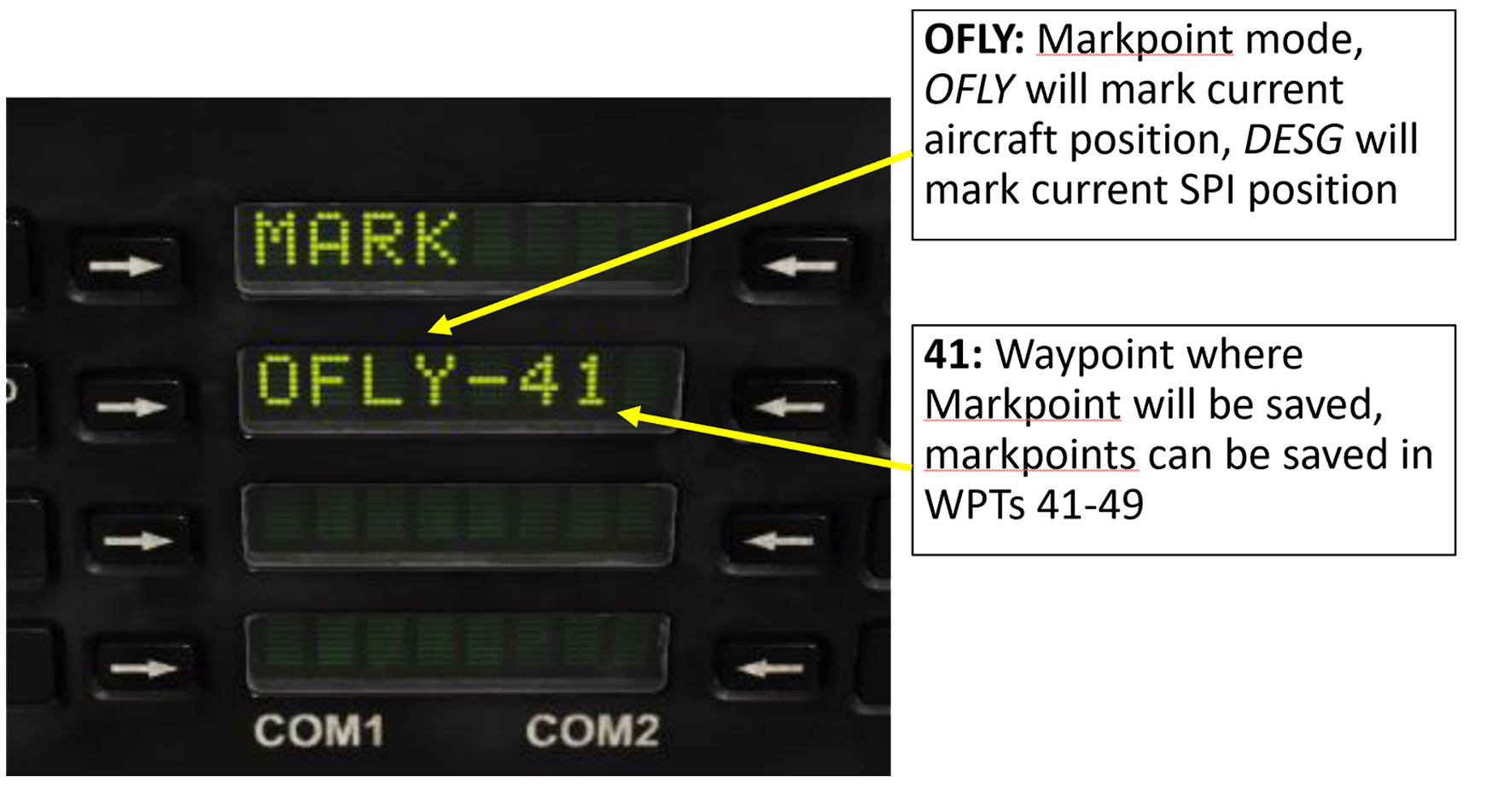
| + | Sets markpoints. There are two ways to set a markpoint, either via OFLY mode which will mark the area the aircraft has overflown or DESG which will mark the current SPI. | ||
| + | [[File:Markpoint.png|400px|thumb|center|Fuel page of the UFCP|]] | ||
=Useful links= | =Useful links= | ||
Latest revision as of 15:50, 7 May 2021
The JF-17 is a low-cost, low-maintenance, lightweight, single-engine, fourth-generation multi-role combat aircraft designed, developed, and produced jointly by the Pakistan Aeronautical Complex (PAC) and the Chengdu Aircraft Corporation (CAC) of China. Designed and built to replace the Pakistani Air Force’s 2nd and 3rd generation fighters such as the Mirage III, A-5, and F-7. The JF-17 entered service with the PAF in 2007, in PAF service it has conducted multiple anti-terrorist operations on the Pakistan-Afghanistan border. The JF-17 has also entered service with the Myanmar Airforce with an order of 16 airframes (of which 7 have been delivered so far).
Capable of carrying multiple types of weapons such as the GPS guided LS-6 and GB-6 and the BVRAAM SD-10 missile it is a very capable airframe. It is also the newest aircraft released as a module in DCS, with its first flight in 2003, only 17 years ago. The version we have in DCS is primarily a Block I with some Block II features: the removable aerial refueling probe being one of the most notable examples of features from the Block II.
Contents
Weapons List
The JF-17 is capable of carrying:
- Mk-82 series 500lbs unguided bomb
- Mk-83 series 1,000lbs unguided bomb
- Mk-84 series 2,000lbs unguided bomb
- Mk-20 cluster bombs
- Hydra 70 2.75 inch rockets
- GSH-23 23mm cannon (A/A & A/G)
- PL-5EII infrared-guided air-to-air missile
- SD-10 active radar homing air-to-air missile
- C-701IR infrared-guided air-to-ground missile
- C-701T television-guided air-to-ground missile
- GBU-10 Paveway II 2,000lbs laser-guided bomb
- GBU-12 Paveway II 500lbs laser-guided bomb
- GBU-16 Paveway II 1,000lbs laser-guided bomb
- LD-10 anti-radiation missile
- GB-6-HE GPS-guided glide cluster bomb
- GB-6-SFW GPS-guided glide SFW-cluster bomb
- GB-6 GPS-guided glide bomb
- LS-6 GPS-guided glide bomb
- CM-802AKG air-to-ground cruise missile
- C-802 anti-ship missile
- BRM-1 Laser-Guided Rockets
- Type-200A Unguided Anti-Runway Bomb
Hotas
The JF-17 has a modern Hands On Throttle And Stick system (HOTAS) which means that most controls the pilot will need in flight will be kept on his HOTAS, thus negating the need to move focus around the cockpit. The Switches on the HOTAS are either named T for Throttle or S for stick. The list of controls is:
On the throttle:
- T1: selects Master Mode
- Up: AA master mode
- Middle: NAV master mode
- Down: AG master mode
- T2: Controls Countermeasures
- Forward: Engages SPJ (Self-Protection Jammer)
- Push: Cages PL-5 seeker
- Backwards: Dispenses Countermeasures
- T3: engages/disengages the Speedbreak
- Forwards: Speed Brake on
- Push: Speed brake on/off
- Backwards: Speed Brake of
- T4: Radio PTT and IFF interrogation:
- Forward: Comm 1 PTT
- Push: IFF interrogation start/stop
- Backward: Comm 2 PTT
- T5: TDC acts as a mouse to slew the various sensors.
- T6: antenna elevation: while in:
- Targeting pod: controls zoom
- A/A radar controls scan elevation
On the Stick:
- S1: Sensor Selection (SS) selects the SOI
- Forward: Selects ACM mode
- Backward: Cycle HUD/Center MFD as SOI
- Right: Select Right MFD as SOI
- Left: Select Left MFD as SOI
- S2: Sensor Control:
- Forward: Increases Display distance and enters Boresight mode when in DGFT master mode
- Backward: decreases display distance and enters vertical scan mode when in DGFT master mode
- Right: Change Azimuth Scan range and enters Heads-Up display area when in DGFT master mode
- Left: in A/A:
- In TWS,RWS or VS mode: cycles between them
- SAM mode: Cycles between SAM and NAM sub-modes
- S3: Weapon release
- S4: Gun trigger
- S5: Missile step / NWS
- S6: Trim
- S7: Autopilot disengage
- S8: cycles between weapon profiles
Cockpit and avionics
Sensor assignment
to select the sensor which you want the TDC to slew press S1 towards the MFD where the sensor is displayed (so if Targeting pod is on the left S1 left will set Targeting pod as SOI). S1 backwards also cycles between HUD and MFD as SOI. A star should appear on the bottom-center of the selected screen to indicate that it is currently SOI.
INS
The JF-17 has an Inertial Navigation System that provides navigational data to the aircraft, it’s systems, and it’s weapons. A Inertial Navigation System works by measuring the rotation, velocity and direction of the aircraft by dead reckoning from it’s initial Position. An INS system is liable to drift, especially with a FAST alignment, however there are multiple ways to correct this drift, the JF-17 corrects the drift by using a Hybrid INS-GPS system, the HNS (Hybrid Navigation System). There are two different modes of alignment, fast alignment and GC alignment, the fast alignment is meant for situations in which GPS is available. Alignment in this mode takes 40 seconds. GC mode does a full alignment and is thus more impervious to drift, it is done in situations where GPS is not available. (or when using GPS guided munitions such as the LS-6 or GB-6). GC alignment takes 3:40 minutes to align.
Alignment Process
Fast
- 1) On the DEST page on the UFCP enter the coordinates and altitude provided in the kneeboard in WPT 0
- 2) Flip the INS knob to FAST
- 3) On the INS page on the MFD enter heading by:
- 4) pressing on the arrow
- 5) enter the Heading provided in the kneeboard
- 6) Wait for remaining time to reach 0:00 and ALIGN on the hud, or FAST on the MFD to start flashing
- 7) Flip INS knob to NAV
Note: if you flip the knob directly to NAV instead of to FAST it will proceed with a FAST alignment but will automatically flip to NAV when alignment is complete.
GC (Full)
- 1) On the DEST page on the UFCP enter the coordinates and altitude provided in the kneeboard in WPT 0
- 2) Flip the INS knob to GC
- 3) Wait for remaining time to reach 0:00 and ALIGN on the hud, or FAST on the MFD to start flashing
- 4) Flip INS knob to NAV
Cockpit
The Jf-17’s glass cockpit is made up of 3 Multi-Color MFDs, a UFC, a HUD and various switches and knobs required for the operation of the aircraft.
AAP
The AAP (Avionics Activation Panel) houses all the buttons that powers on the various avionics of the JF-17 via it’s labelled buttons; Green means powered on. Pressing ‘’’CMBT’’’(1) will power on all Avionics required for an A2A mission and ‘’’TRAIN’’’’(2) will turn on all avionics required for a basic training mission (no weapons employment). Each avionic can also be powered on/off individually by clicking on the corresponding button. An important thing to remember is that the TPOD and SPJ are not powered on automatically. To turn on the TPOD the ‘’’CLDP’’’(3) button must be clicked. And ‘’’SPJ’’’ to power on the jammer pod(4). Note: HMD and the IRST buttons are currently not functional.
MFCDs
The JF-17 has 3 large format Multi Function Colour Displays as its primary instrumentation for flight in addition to the HUD and the UFCP. Each MFCD is fully capable of displaying full colour imagery and is divided into two sections, a Primary Display along the top and a Secondary Display underneath, sectioned off by a white dividing line. The MFCDs are controlled using a series 26 On Screen Buttons, 8 along the left and right and 5 along the top and bottom. Control of the image over the entire MFCD is accomplished by 3 rocker switches in the top right, bottom right and bottom left corners, controlling Symbology Brightness, Image Contrast and Image Brightness respectively, and power is controlled through a 2 position rotational switch in the top left corner, initialised to on by default.
Primary Display Pages are accessed either through the Main Menu Page, through the Data Submenu for Data Pages, or using the quick access OSBs at the bottom of the MFCDs. The default displays are assigned based on the current selected Master Mode. Primary Display Pages are controlled either through the HOTAS or by using the 5 Top OSBs and the first 5 Left and Right OSBs. The Centre Bottom OSB is always used to return the MFCD Primary Display to the Main Menu.
Secondary Display Pages are controlled using the lower 3 Left and Right OSBs and accessed through a Secondary Main Menu accessed through the Bottom Right OSB labelled RTN.
Quick access buttons are assigned as such:
- Left MFCD: CMBT/SMS, unless SMS selected in which case CMBT/JETT
- Centre MFCD: RDR/(Blank)
- Right MFCD: HSD/CLNK
And pages will default to:
- Left MFCD: SMS unless in NAV Master Mode in which case EFIS
- Centre MFCD: RDR
- Right MFCD: HSD
UFCP
The UFCP (Up Front Control Panel) is similar in function to the hornet and Harrier’s UFCs On the left is a standard numerical keypad which are also used to enter different UFCP Functions (pages, Menus) when not entering data. On the center of the screen are 4 green lines surrounded by arrows on both sides by arrows (the UFCP Data Field and Data Field select buttons), you click on these arrows to edit the data you want to input on the data field. On the left of the Datafield are The UFCP Priority Functions, these enter various functions on the UFCP. under the UFCP between the HUD brightness knob and the HUD standby reticle knob is a dobber switch that can be used to quickly increase the selected value, for example if you are on WPT 1 and wish to switch to 2, instead of entering 02 on the Keypad you click + on the dobber switch, and it will increment upwards towards WPT2.
The “Main Menu” of the UFCP is clicked by pressing RTN on the keypad, this will return you to the main page no matter what display you are on. (unless you are entering data in which case it will cancel it). The Main page consists of the current selected Flight plan at the top, in our case FP-A, along with the current selected waypoint on the right of the FP. right under that there is the switch between CAS and TAS, (Calibrated Air Speed and True Airspeed) and to the right of that is the AUTO/MAN switch which toggles the automatic sequencing of Waypoints. Then at the very buttom are the two radios, Comm 1 and Comm 2 displaying the current preset Frequency.
Important UFCP functions are:
DST
DST (Destination) is for the entering and editing of waypoints, top entry line has the current waypoint being edited on the right, and below that are the Coordinates in DD*MM’SS.S and at the very bottom is the altitude of the Waypoint.
Fuel
Sets the current Bingo fuel. When this the fuel readout reaches this amount a warning will be given. If Waypoint mode is set to AUTO the EMMC will be set to BINGO and waypoint 50 (Home Plate) will be selected.
IFF
WIP
MRK
Sets markpoints. There are two ways to set a markpoint, either via OFLY mode which will mark the area the aircraft has overflown or DESG which will mark the current SPI.
Useful links
- Chuck's guide for JF-17
- JF-17 discussion forum
- Deka Ironworks' "DCS JF-17" playlist in YouTube
- RedKite's playlist in YouTube with a collection of tutorials by Deka, Jabbers, RedKite
- JF-17 Training Missions by Rudel-Chw

