Difference between revisions of "User:Jak/Sandbox2"
(→Advanced Multipurpose Color Display (AMPCD)) |
(→{{anchor|HSI Courseline Steering Cues}}Courseline Steering Cues) |
||
| Line 473: | Line 473: | ||
[[File:HSI Format - Course Cues|526px|center]] | [[File:HSI Format - Course Cues|526px|center]] | ||
| − | #'''Courseline''' - A line is drawn through the point for which a course is defined. | + | #'''Courseline''' - A line is drawn through the point for which a course is defined. The arrow on the line indicates the direction of the course, so as to differentiate reciprocal courses. |
| − | #'''Distance from Course''' - | + | #'''Distance from Course''' - The distance from ownship to the closest point on the courseline is indicated here in hundredths of a nautical mile (X.XX). |
====Markpoint Creation (MK#) Function==== | ====Markpoint Creation (MK#) Function==== | ||
Revision as of 22:27, 29 July 2021
Contents
- 1 Avionic System Introduction
- 2 Navigation Systems
- 2.1 Navigation in A/A Master Mode
- 2.2 Navigation in A/G Master Mode
- 2.3 Navigation Equipment
- 2.4 Navigational HUD Symbology
- 2.5 Horizontal Situation Indicator (HSI) Format
- 2.6 Flight Performance Advisory (FPAS) Format
- 2.7 Automatic Flight Control System (AFCS)
- 2.8 Automatic Throttle Control (ATC)
- 2.9 Inertial Navigation System (INS)
- 2.10 Communication Radios
Avionic System Introduction
The F/A-18 avionic system is the computer interface with most of the aircraft systems. This section provides an overview of the displays and inputs used to interact with the avionics.
The avionics displays information to the pilot through three screens, a projected Head-Up Display (HUD), and a Helmet Mounted Display (HMD), termed the Multipurpose Display Group (MDG). The pilot gives inputs to the system using pushbuttons on the MDG screens, the Up-Front Control (UFC) panel, and the Hands On Throttle and Stick (HOTAS) controls.
Multipurpose Display Group
The Multipurpose Display Group (MDG) is the avionic system output to the pilot and a point of pilot input to the avionics.
The primary flight instrument is the Head-Up Display (HUD), which displays flight instruments in addition to navigation, sensor, and weapon cuing. The Helmet Mounted Display (HMD) duplicates the HUD symbology with some additional capabilities. The left Digital Display Indicator (DDI), the right DDI, and the center Advanced Multipurpose Color Display (AMPCD) are the main "heads-down" displays and provide the majority of system interfaces. Multifunction pushbuttons on the DDIs/MPCD let the pilot select labeleled options. More complex data entry (e.g. position coordinates) and accessing certain functions is accomplished with the Up-Front Control (UFC) located below the HUD between the DDIs (see Up-Front Control).
Head-Up Display (HUD)
The Head-Up Display (HUD) is a display projected onto a glass at the front of the cockpit. The projection is collimated, which means the symbology is focused at infinity. This allows symbology to be accurately overlayed on the outside world regardless of the angle and distance from which the pilot is looking at the HUD. This is vital for displaying symbols that represent a real position in 3D space, such as a target on the ground.
There is a very large amount of possible HUD symbology that may be displayed. The universal symbology for basic flight and navigation is described under Navigational HUD Symbology.
Helmet-Mounted Display (HMD)
The Helmet-Mounted Display (HMD) is a display fixed to the helmet. Unlike the HUD, the HMD symbology can always be seen regardless of where the pilot is looking. The HMD in the F/A-18 is the Joint Helmet Mounted Cueing System (JHMCS) and these terms are used interchangeably. The nature of the HMD permits some unique functionality; for example, the pilot can see a symbol for a target in the air or on the ground that is outside the field of view of the HUD.
The HMD replicates most symbology found on the Head-Up Display. HMD-unique symbology is specifically described in the appropriate sections. Otherwise, the symbology described for the HUD is applicable also to the HMD except where specifically noted.
Digital Display Indicators (DDIs)
The multifunction displays for interfacing with most of the aircraft systems are the left and right Digital Display Indicators (DDIs). The center AMPCD has the same functionality.
On the DDIs, as well as the AMPCD, the pilot is able to display many pages or "formats." Formats display information and allow for interfacing and control with various systems.
The DDIs are tri-color with green, yellow, and red capability. The primary color used in the avionics is green. Yellow is associated with a few things like cursors and unknown or ambiguous targets. Red is associated with hostile targets.
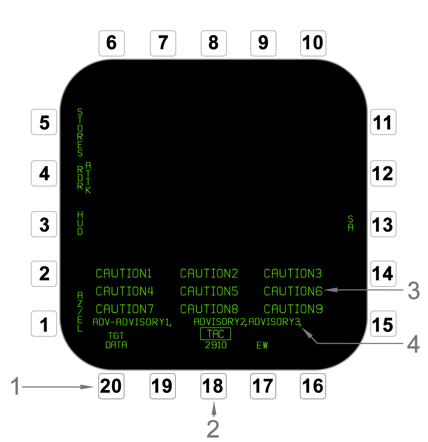
- Pushbuttons (PB) - There are 20 pushbuttons (PBs) located around the display. A PB has an associated label for its function depending on the selected format/subformat/etc. The PBs are numbered clockwise from the bottom left as illustrated.
- Menu Option - PB18 serves as a universal "return to menu" option. When selected from any other format it invokes the Tactical Menu format. From there it will cycle between the Tactical and Support Menu formats (refer to Menu Formats). Above the pushbutton, with weight off wheels, a four digit system time is displayed for maintenance use. With weight on wheels, it reads MENU.
- Cautions - On the left DDI, the caution bank is displayed in large text. Cautions are any critical scenarios the pilot needs to be aware of pertaining to the aircraft systems. Generally this is limited to fuel, electrical, and hydraulic systems critical to flight safety. If either the total cautions exceed 9, the left DDI is off, or if it is displaying the BIT or Infrared Maverick format, the cautions will "spill over" to the AMPCD and then right DDI in that order.
- Advisories - On the left DDI, advisories to the pilot are displayed on this line after the word ADV-. These are non-critical pieces of information for various systems. New cautions are initially displaced to the right. When the Master Caution light is extinguished and then pressed again (twice in total), existing advisories "stack" close together to the left. Each advisory is separated by a comma.
Menu Formats
All the available formats are selected from one of the two main menu formats. These are the Tactical (TAC) Menu and Support (SUPT) Menu formats. In general, the formats on the Tactical Menu are sensor and weapon oriented, while the Support Menu is oriented toward utility and navigation. Certain formats are not not always available and so will not always be displayed on the menus.
The Tactical Menu is accessed at anytime using PB18 on either left or right DDIs or the AMPCD. PB18 will then cycle between the Tactical Menu and Support Menu formats. Either TAC or SUPT is indicated above PB18.
| Menu Format (PB18) Cycling |
Advanced Multipurpose Color Display (AMPCD)
The AMPCD (often just called the MPCD) is a multifunction display in the bottom center of the front panel. It has identical function to the DDIs, except is full-color capable. This is used to (optionally) display a colored background map on the Horizontal Situation Indicator (HSI) navigation format and the Situational Awareness (SA) air-to-air format.
Identically to the DDIs, there are 20 pushbuttons (PBs) around the AMPCD. The DDI formats are all accessible on the AMPCD except the A/G Radar format. The AMPCD is most frequently used for the HSI or SA format.
Up-Front Control (UFC)
The Up-Front Control (UFC) is located at the center of the front panel directly beneath the HUD. The UFC is used for data entry as well as interfacing with some aircraft functions that have been placed on the UFC instead of the DDI/AMPCD-accessible formats.
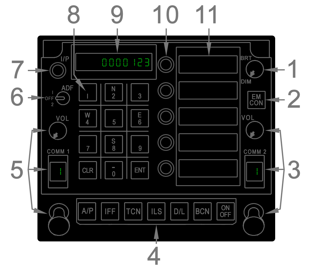
- Brightness Knob - This knob controls the brightness of the scratchpad and option display windows.
- EMCON Button - The EMCON button toggles the Emission Control mode on/off, which disables any radio emissions. The letters E M C O N are displayed in the option display windows. Refer to Emission Control (EMCON) Mode.
- COMM2 Radio Controls - These are controls for the COMM2 radio. Refer to Communication Radios.
- Function Selector Buttons - The bottom row of buttons select a particular UFC format for a given function. The ON/OFF button is context dependent and usually turns the selected function on or off. When a function is on, ON is displayed in the left portion of the scratchpad and otherwise it is blank. For information on these individual functions refer to: Automatic Flight Control System (AFCS) for A/P; Navigation Equipment for TCN and ILS; Combined Interrogator/Transponder (CIT) for IFF; and Multifunction Information Distribution System (MIDS) for D/L.
- COMM1 Radio Controls - These are controls for the COMM1 radio. Refer to Communication Radios.
- ADF Switch - This switch is used to manipulate the Automatic Direction Finder (ADF). Refer to Automatic Direction Finder (ADF).
- I/P - The I/P (identification of position) commands the Combined Interrogator/Transponder to briefly reply to Mode 1/2/3 interrogations with the "IDENT" signal. This is intended for use upon air traffic control instruction.
- Keypad - The keypad consists of numbers 0–9, an enter (ENT) key, and a clear (CLR) key. The 2, 4, 6, and 8 keys are used to define a northing/southing or a westing/easting for coordinate entry in certain contexts. The CLR key wipes anything currently in Scratchpad. The ENT key sends the scratch pad data to whatever function is being manipulated by the UFC. When the entered data is valid, the data is removed from the scratchpad. When the entered data is invalid, the word ERROR flashes in the scratchpad window until cleared.
- Scratchpad Window - The scratchpad window displays either the data inputted via the keypad prior to entry and/or the ON or OFF status of a particular function.
- Option Select Buttons - A single option select button is located adjacent to each option select window. They are used to select the option in the corresponding window. Depending on the context it may select a type of data for entry, select/deselect a mode, or cycle through different modes. Selecting an option is termed "colonizing" it because a colon symbol (:) in the window indicates the selection.
- Option Display Windows - The five option display windows can display selectable options. These may either be modes toggled with the adjacent option select buttons or be types of data which must first be selected before the actual data can be typed in via the keypad. In both cases, the selected option is "colonized" with a colon (:) displayed on the left side of the window.
Master Modes
Air-to-Ground (A/G)
Air-to-Air (A/A)
HOTAS Controls
Control Stick
Throttle
The F/A-18 is equipped with expansive navigation capabilities. The Head-Up Display (HUD) provides all the needed instrumentation to fly and easily steer/navigate the aircraft. The Horizontal Situation Indicator (HSI) format provides more detailed information, a top-down situational picture, and an interface with the various navigation-related functions like steering mode selection and waypoint editing. The HSI is typically displayed on the AMPCD, but can be put on any display.
The avionics stores a set of navigation waypoints, which are arbitrarily definable points in space. These can be leveraged for navigational and/or tactical application. The aircraft is also equipped with Tactical Air Navigation (TACAN) and Automatic Direction Finder (ADF) equipment which can be used for flying under instrument flight rules (IFR). For the carrier environment, the aircraft is able to use the Instrument Carrier Landing System (ICLS).
The Automatic Flight Control System (AFCS) and Automatic Throttle Control (ATC) serve to lessen pilot workload. The AFCS includes basic attitude hold functions as well as the ability to automatically fly the aircraft to navigation points or to intercept courses. The ATC can hold a cruise speed or an angle of attack on final approach.
Waypoint Database
The computer stores a digital database of waypoints. A few types exist. "Waypoints" are simply customizable positions in space with a longitude, latitude, and altitude stored. The aircraft stores up to 60 Waypoints (0-59) and 9 Markpoints (1-9). For each Waypoint, offset bearing and range can be inputted to make an Offset point. Waypoints are termed Offset Aim Points (OAPs) when offset data is applied to them.
In summary the types of Waypoints are: basic Waypoints, Markpoints, Offsets, and Offset Aim Points (OAPs).
Waypoints can be edited on the Waypoint Data sublevel of the HSI format or can be pre-loaded with the AMU (refer to Waypoint Data Sublevel). Markpoints are only created in-flight, using the HSI format (refer to Markpoint Creation Function). The position of the selected Waypoint/OAP/Markpoint is visualized on the HSI format. Steering cues are provided on the HSI format and on the HUD (refer to HSI Format and Navigational HUD Symbology).
Waypoints/OAPs are also assigned to one of three "Sequences". Each Sequence is simply a set of Waypoints in a set order, so they can be thought of as routes. The full route can be displayed as a line on the HSI format according to the order of the Waypoints in the Sequence.
The A/G Designation (target) behaves very similar to waypoints. It can be steered to and displayed on the HSI format and HUD. The location of any kind of waypoint can be used to make the Designation, but it can also be created and changed with other sensors such as the FLIR. Refer to A/G Designation.
The F/A-18 is equipped with a Tactical Air Navigation (TACAN) terminal which allows TACAN signals to be received and transmitted. The terminal reaches land- or sea-based stations as far away as 390nm and airborne stations at 200nm.
The TACAN is powered on, tuned, and configured using the UFC (refer to UFC TACAN Format). The pilot navigates to TACANs using the cues on the HUD and/or HSI format. The HUD and HSI also display information on the tuned station such as its ID, distance, and bearing. Refer to Navigational HUD Symbology and HSI Format.
TACAN can also be used as an INS position keeping source. Refer to HYPERLINK.
The TACAN terminal is combined with the Multifunction Information Distribution System (MIDS) equipment (see HYPERLINK). This causes limitations in usable TACAN frequencies. These are detailed in Channel Limitations.
UFC TACAN Format
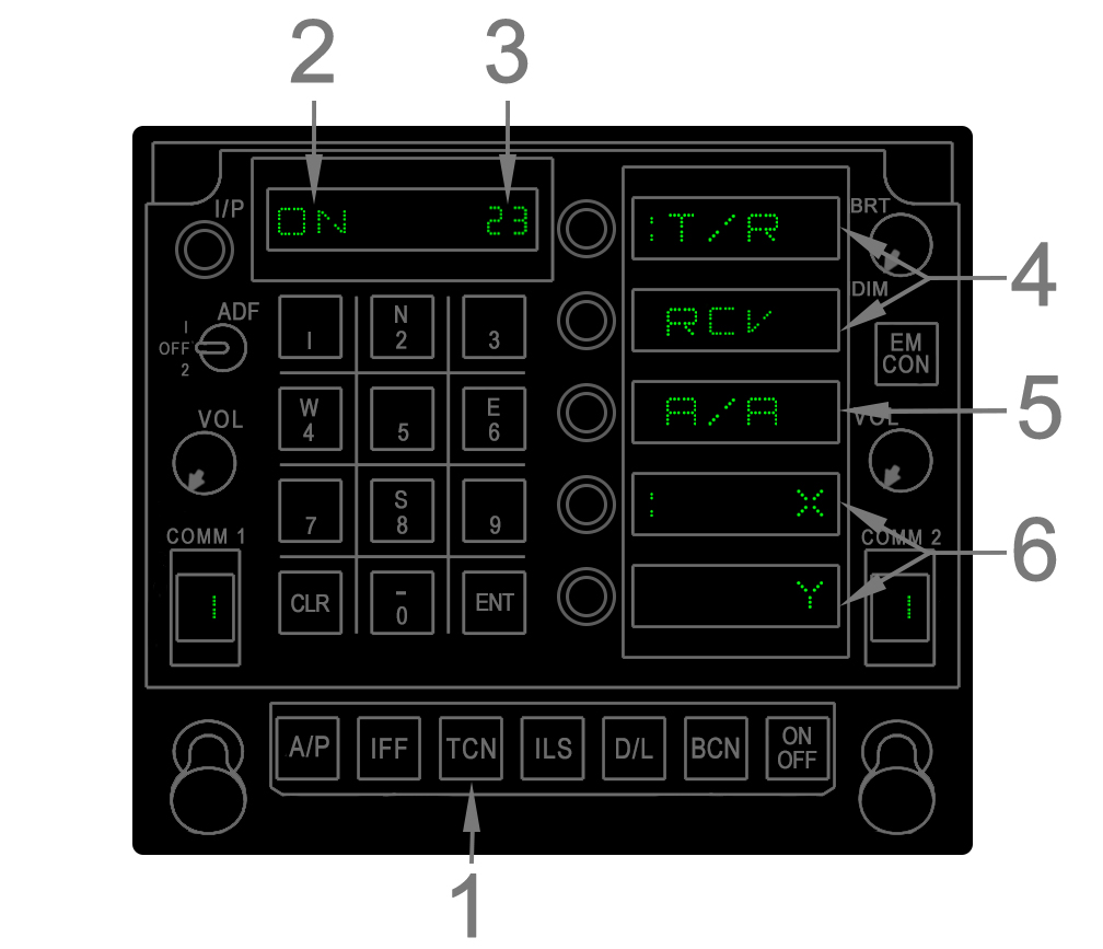
- TCN Button - Pressing the TCN button invokes the TACAN format on the UFC. The TACAN format remains display until another one is invoked or if the UFC times out and blanks.
- TACAN Status - The scratchpad will read ON when the TACAN terminal is powered and is blank otherwise. Power is toggled by pressing the ON/OFF button on the UFC for at least 1 second.
- Tuned Channel - The one, two, or three digit numeric TACAN channel is displayed here. A new channel can be tuned via the keypad by entering one or two numbers and then selecting ENT. The X or Y band is selected at OSB4/5.
- Transmit/Receive Toggle - The main modes for using land-based TACANs are Transmit and Receive (T/R) and Receive-only (RCV) mode, which are switched by colonizing the appropriate option select window. In T/R mode allows the aircraft to transmit to and therefore compute slant range with the station. In both modes the aircraft receives bearing to the station. T/R and RCV are mutually exclusive with the A/A mode.
- A/A Mode Select - The A/A (air-to-air) mode is used with airborne TACANs and is mutually exclusive with the T/R or RCV land-based modes. In A/A, the TACAN terminal only gets slant range via single-pulse transmitting/receiving.
- X/Y Band Toggle - Colonizing either X or Y tunes the terminal to that channel band.
Channel Limitations
The TACAN terminal is impacted by it being integrated with the Multifunctional Information Distribution System (MIDS) terminal. A few limitations apply with regard to the TACAN channels which can be used.
In A/A mode, channels 1–36X/Y and 64-69X/Y are unusable because the upper antenna filters out these frequencies to alleviate MIDS interference.
In T/R or RCV mode, channels 1-29X/Y, 47-63X, and 64-92Y are degraded when a center fuel tank is loaded. This is because only the lower antenna can use these channels, which is blocked at rear aspect angles. This significantly impacts functional range when flying directly away from a TACAN. This varies between 20-50 miles based on altitude. Left, right, and front aspect angles are not impacted.
A/A Yardstick Broadcast
The TACAN system can act as its own airborne pseudo-station, termed a yardstick. This provides slant range (not bearing) to up to five other airborne TACAN-capable aircraft.
To broadcast a yardstick, the following procedure applies:
- TACAN is set to A/A mode.
- Yardstick host channel is spaced 63 channels apart from the receiving aircraft in the same band (e.g. 40Y and 103Y).
The result is that the aircraft will receive slant range from any other A/A TACAN capable aircraft and those aircraft will receive their distance from ownship.
Note that when broadcasting a yardstick received by multiple aircraft (up to 5), the range received by the host may erratically change as the terminal is receiving multiple aircraft.
Instrument Carrier Landing System (ICLS)
An Instrument Carrier Landing System (ICLS) is equipped on the F/A-18. The ICLS provides precision lateral and vertical approach guidance for carrier landings. ICLS is required in certain types of instrument-based carrier operations. Note that the abbreviation "ILS" and "ICLS" are used interchangeably; the F/A-18 is not equipped with a civilian instrument landing system.
ICLS system power and the tuned channel is set on the UFC. ICLS steering cues are displayed on the HUD when selected on the HSI format and are described in ICLS Steering Symbology.
UFC ICLS Format
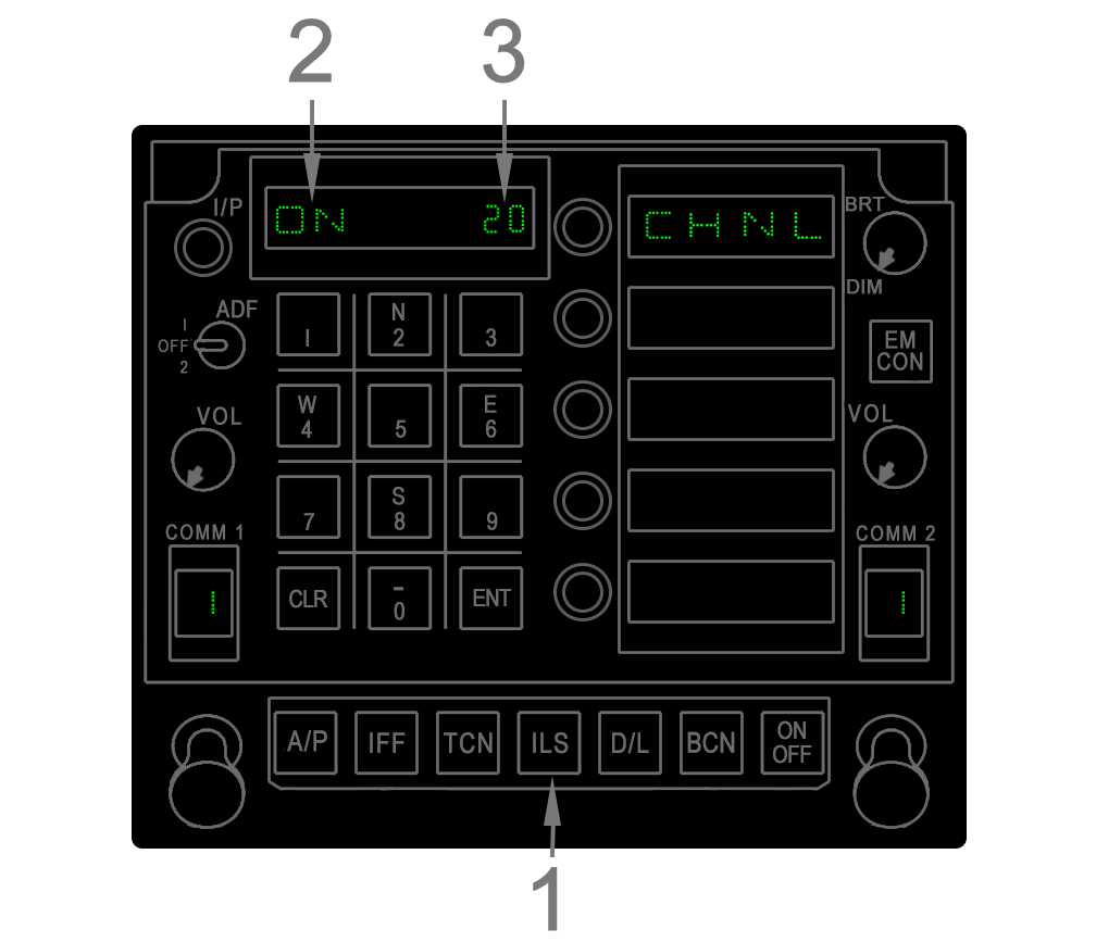
- ICLS Function Key - Pressing the ILS button invokes the ICLS format on the UFC. The ICLS format remains displayed until another one is invoked or if the UFC times out and blanks.
- ICLS Status - The scratchpad will read ON when the TACAN terminal is powered and is blank otherwise. Power is toggled by pressing the ON/OFF button on the UFC for at least 1 second.
- Channel - The tuned ICLS channel is displayed in the scratchpad. The channel is changed by entering the digits on the keypad and then pressing ENT.
Automatic Direction Finder (ADF)
The F/A-18 is equipped with a VHF/UHF Automatic Direction Finder (ADF) which provides bearing information to a radio signal in the 100–400 Mhz frequency range. The ADF can be used in certain instrument flight rules procedures.
ADF power is controlled via the ADF switch on the UFC; see UFC for its location. The pilot sees the ADF bearing by a cue on the HSI format.
ADF Operation
The ADF switch on the UFC has three positions. In the OFF position, the ADF system is off. The 1 and 2 positions power the ADF on and feed it either the COMM1 or COMM2 radio frequency.
Once powered, the ADF bearing is displayed on the HSI format. This takes the form of a circle shape that is positioned around the HSI compass rose. See HSI Format and HSI Symbols Legend for details.
When the ADF is on, the raw audio from the tuned station is passed through the selected radio (COMM1 or COMM2) and so can be controlled using the appropriate volume knob on the UFC.
This section covers the fundamental flight instrumentation and all navigation cuing that can be displayed on the Head-Up Display (HUD). With a few exceptions noted, most of the flight and navigation symbology is common throughout all master modes.
A wide range of weapon and sensor related symbology can also be displayed on the HUD depending on various factors. This symbology is detailed in the relevant sections.
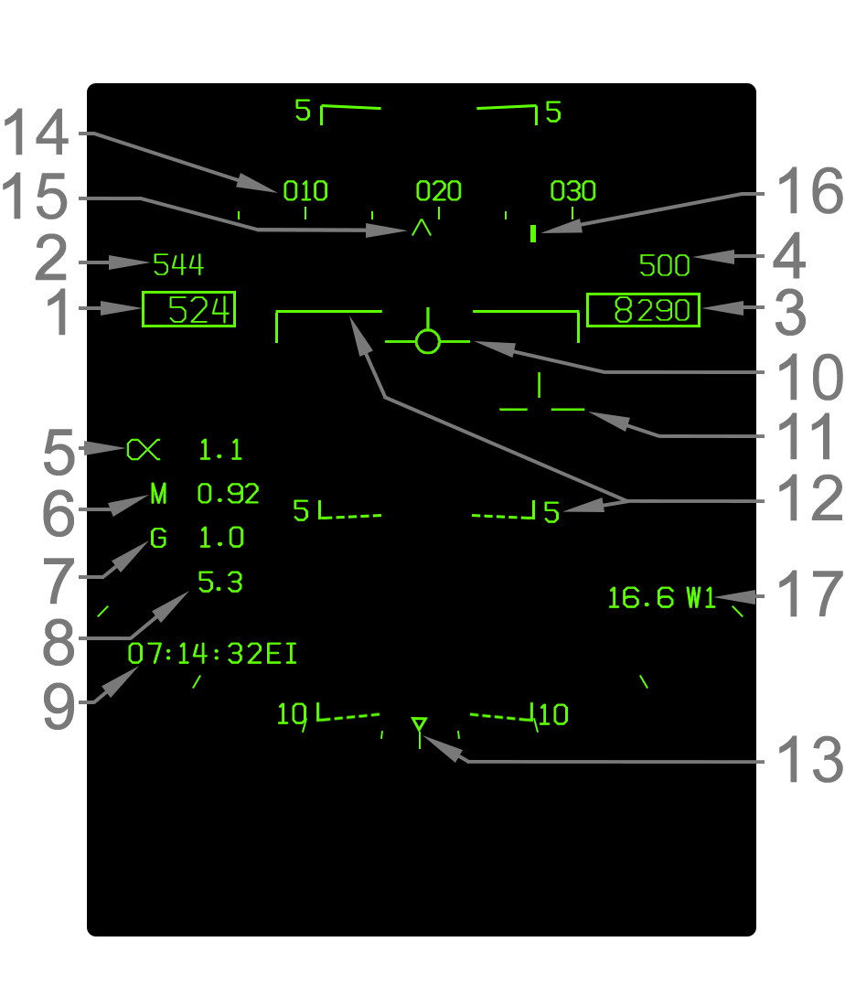
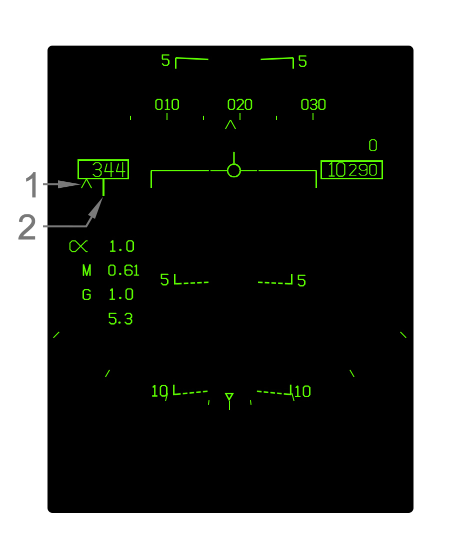
- Indicated Airspeed - Indicated airspeed (IAS) in knots is displayed in this box.
- Best Climb Airspeed - When CLIMB is boxed on the FPAS format, the best climb airspeed is displayed above the current airspeed. This is only displayed in NAV master mode.
- Altitude - Altitude is displayed in feet in this box. When the altitude source switch is set to BARO, barometric altitude above mean sea level (MSL) is displayed. If the switch is set to RADAR, radar altimeter altitude above ground level (AGL) is displayed if valid. If the radar altitude is not valid, barometric altitude is displayed and a flashing "B" appears. For details see Altitude Source.
- Vertical Speed - Vertical speed in feet per minute (fpm) is displayed directly above the altitude box. A negative value (losing altitude) is prefixed with a minus (-) sign. The vertical speed is only shown in NAV master mode.
- Angle of Attack - Current angle of attack (AOA)/alpha is indicated here next to the Greek alpha symbol. The AOA is blanked when the gear is down and the aircraft is "on speed" (AOA between 6.9° and 9.3°).
- Mach Number - Current speed as a percentage of the speed of sound (Mach number) is indicated here.
- Current G - The current G-force experienced by the aircraft is indicated here.
- Peak G - The highest G-force experienced is indicated here if that peak G-force was more than 4.0G. The peak G is reset when the HUD symbology reject switch is cycled to REJ1 (or REJ2) and back to NORM.
- Time Window - Either the current Zulu time (abbreviated EI), a countdown timer (CD), or an elapsed time (ET) can be displayed in this area of the HUD. This is configured with the TIMEUFC function on the HSI format.
- Velocity Vector - The velocity vector indicates the actual vertical flight path angle and, when uncaged, the horizontal flight path (accounting for wind drift/yaw) as well. When the ghost velocity vector is displayed (caged velocity vector operation), then this velocity vector is displayed near the center of the HUD and does not indicate true horizontal drift. Refer to Caged/Uncaged Velocity Vector Behavior. The velocity vector flashes if its position is outside the HUD field of view. A dot appears in the center of the velocity vector when the TDC is assigned to the HUD.
- Ghost Velocity Vector - The ghost velocity vector is displayed when the HUD is caged and appears as a segmented version of the velocity vector. Its purpose is to indicate the real horizontal flight path angle of the aircraft with regard to wind drift, while the regular velocity vector remains near the center of the HUD. Refer to Caged/Uncaged Velocity Vector Behavior. The ghost velocity vector flashes if its position is outside the HUD field of view.
- Flight Path/Pitch Ladder - The flight path/pitch ladder indicates either the true flight path angle (typically) or the nose pitch. Each bar is placed in 5° increments, with angles below the horizon being dashed. For details, refer to Flight Path/Pitch Ladder Behavior. The ladder is always oriented upright relative to the horizon. This is used with the velocity vector, which is always oriented to the aircraft itself, to visualize aircraft roll.
- Bank Angle Scale - Aircraft bank angle is indicated by this scale and the triangle caret that moves along it. The ticks are placed on both the left and right sides at 5°, 15°, 30°, and 45° increments. The triangle is limited just past the final tick at 47°. When bank is greater than 47°, the triangle flashes.
- Heading Scale - The heading scale indicates the current magnetic or true heading of the aircraft in conjunction with the heading caret. The heading scale is simply a compass. It is not to scale; in other words the ticks on it are not scaled to the outside world on the HUD. Note that the heading scale is shifted up 1.25° from its position in NAV master mode when in A/G or A/A master mode.
- Heading Caret - This caret simply indicates the current aircraft heading on the heading scale. This does not indicate actual aircraft ground track corrected for wind drift, but only the heading of the nose. When the heading reference is set to true north on the HSI format, the caret becomes a letter "T".
- Command Heading Cue - The command heading cue indicates the commanded heading to steer to the selected Waypoint, OAP, Offset, Markpoint, TACAN, or Designation. The command heading cue, although commanding a heading, is corrected for wind drift so that flying the commanded heading will place the aircraft's ground track at the desired point and not necessarily point its nose directly at it. As such, using the command heading cue simply involves turning the aircraft such that the command heading cue and the heading caret are lined up. The cue becomes a diamond shape when steering to the A/G Designation.
- Navigation Range Cue - Range in nautical miles to the selected steer-to point is displayed here. This can be a Waypoint/Offset Aim Point, Offset, Markpoint, TACAN, or the A/G Designation. The range to a waypoint is suffixed by a letter: W (Waypoint or OAP), O (Offset), or M (Markpoint), and the associated number; e.g. "W2" for Waypoint 2. A TACAN is suffixed by its three-letter identifier. The A/G Designation is suffixed by TGT (target). Range to anything but TACAN is range over the ground and range to TACAN is slant range.
Altitude Source
The altitude window on the HUD displays either altitude above mean sea level (MSL) from the barometric altimeter or altitude above ground level (AGL) from the radar altimeter. The display is primarily a function of the altitude source switch located just below the UFC.
When set to BARO, barometric altitude is displayed invariably. However, when set to RDR, radar altitude is only displayed when valid and is indicated by a letter "R". When invalid, barometric altitude is displayed even though the source is set to radar. This scenario is indicated by flashing "B". Radar altitude is considered valid when a value of 5,000ft or less is received.
Note that it is possible for the radar altitude to be valid but relatively inaccurate. This is because the radar altimeter is angled directly away from the belly of the aircraft. It does not always look straight down. As such, an inaccurate radar altitude occurs in steep bank/pitch angle scenarios where the altimeter is outputting a slant distance greater than the actual distance between the aircraft and the ground directly below. The only time the radar altimeter is truly free of any slant error is at 0° pitch and roll.
| Selected altitude source | Barometric altitude | Radar altitude | |
| Radar altitude is valid | Radar altitude is invalid | ||
| Altitude displayed on HUD | Barometric altitude | Radar altitude with solid "R" | Barometric altitude with flashing "B" |
Flight Path/Pitch Ladder Behavior
The flight path/pitch ladder on the HUD is typically in fact a flight path ladder, in that it is positioned relative to the velocity vector. The pitch ladder drifts horizontally with the velocity vector. When the HUD is caged, the pitch ladder is aligned with the caged velocity vector so that it remains near the center of the HUD.
Whenever the velocity vector which the pitch ladder is aligned with is outside the HUD field of view (FOV), the ladder shifts to the center of the HUD and is then positioned relative to the aircraft waterline instead. The waterline is indicated by a "W" symbol whenever the velocity vector is outside the HUD field of view. In this scenario, it only indicates pitch relative to the waterline (nose) and not the flight path. Note that when the velocity vector is caged, if only the ghost velocity vector is outside the HUD, no change with the flight path ladder occurs since it is aligned with the caged velocity vector. The caged velocity vector will only escape the HUD FOV in extreme yaw/crosswind scenarios in a bank.
The pitch/flight path ladder contains "rungs" in 5° increments. The horizon itself is indicated by a solid line. Angles above the horizon are solid as well, while angles above are dashed. The rungs are slanted toward the horizon by half the amount of the angle which they represent. For example, the -5° line is slanted 2.5° upward (toward the horizon) and the +10° line is slanted 5° downward.
Caged/Uncaged Velocity Vector Behavior
The velocity vector can either be "caged" or "uncaged". In NAV master mode, this can be toggled with the Cage/Uncage button on the throttle. In A/G master mode, the HUD is always caged. In A/A master mode, the HUD is always uncaged.
When the velocity vector is caged, the "regular" velocity vector is horizontally displayed near the center of the HUD (caged). Navigational cuing is referenced to the caged velocity vector. This makes the HUD easier to read at significant yaw or crosswind components. When the true horizontal flight path angle differs from the ghost velocity vector position, a segmented "ghost" velocity vector is displayed to show the real flight path. However, this ghost velocity vector is blanked within 2° to prevent clutter since there will always be at least a fractional angle difference. In terms of vertical flight path angle, both velocity vectors indicate the real angle.
Note that anytime the aircraft is in a bank, the caged velocity vector may not always be precisely on the center of the HUD, but close to it. This is due to the fact the caged velocity vector has to indicate the true vertical flight path angle while also maintaining the same distance from the ghost velocity vector as the distance between the ghost velocity vector and the aircraft waterline/heading.
When the velocity vector is uncaged, only one "regular" velocity vector is displayed which always indicates the true horizontal (and vertical) flight path angle.
Caged Velocity Vector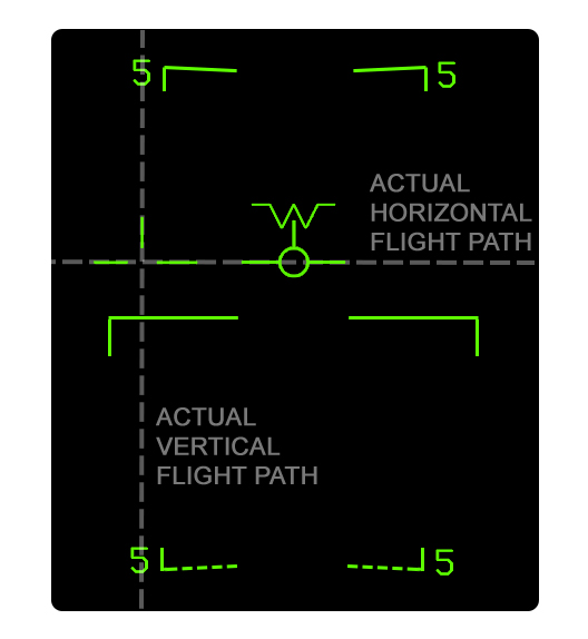
|
Uncaged Velocity Vector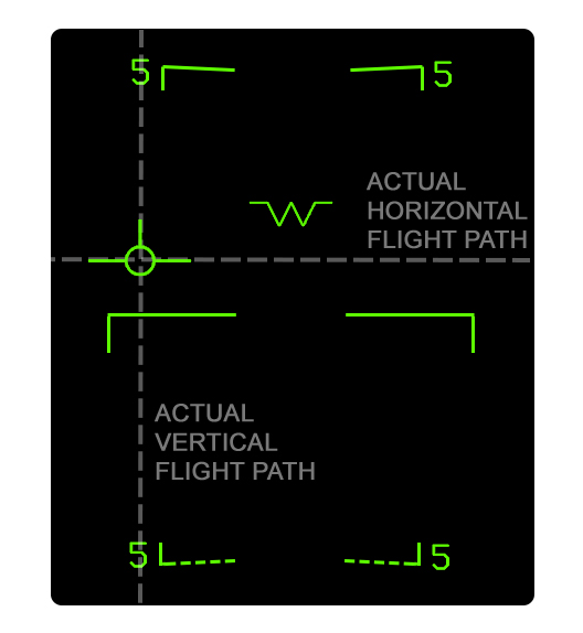
|
Symbology Reject Modes
HUD symbology can be decluttered, or "rejected", using the switch just under the Upfront Controller (UFC). There are three settings: NORM, REJ1, and REJ2. The following symbology is rejected. All symbology rejected in REJ1 is also rejected in REJ2.
| Removed in REJ1 | Removed in REJ2 |
| Mach number | Heading scale |
| G-force | Navigation range cue |
| Peak G-force1 | Time window |
| Bank angle scale | |
| Box around airspeed | |
| Box around altitude | |
| Time on target symbology | |
| 1 Peak G value is reset when switch is returned to NORM | |
Landing Symbology
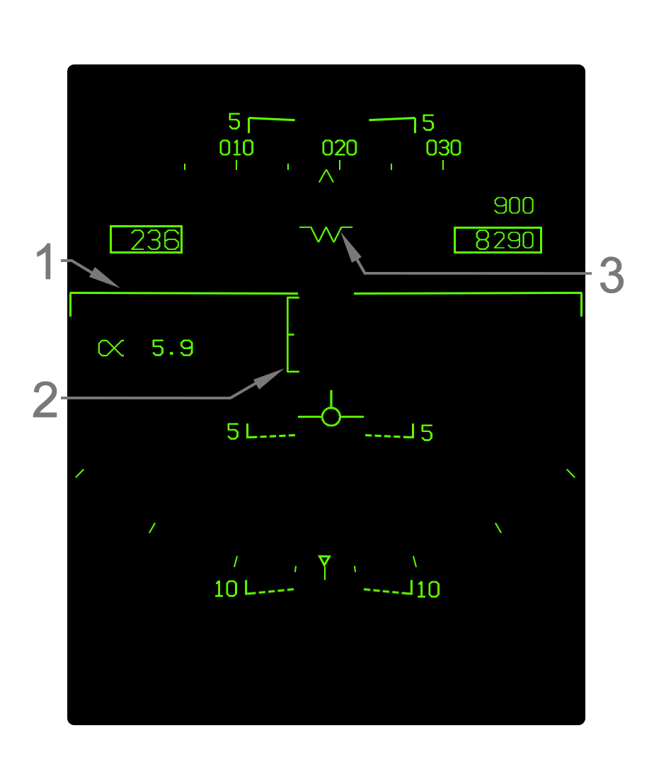
When the landing gear is down and locked, NAV master mode is automatically selected and some changes to the HUD are made. In addition to the symbology illustrated, the Mach, G, and peak G numbers are removed. AOA is also removed when the velocity vector is within the AOA bracket.
- Elongated Horizon Line - When the gear is down, the horizon line is elongated as such.
- Angle of Attack Bracket - The angle of attack (AOA) bracket indicates the optimal region of AOA for landing. The bracket is positioned relative to the velocity vector. For details refer to Angle of Attack Bracket. Note that the actual AOA readout on the HUD is blanked when the velocity vector is within the AOA bracket.
- Waterline Symbol The aircraft waterline is indicated by this "W" symbol whenever the gear is down or otherwise whenever the velocity vector is outside the HUD field of view. The waterline is essentially the nose reference of the aircraft; it indicates aircraft pitch rather than the actual vertical flight path angle, which is indicated by the velocity vector. The waterline symbol is coincident with the tops of the airspeed and altitude boxes which can be used for reference since the waterline symbol is not displayed most of the time when the gear is up.
Angle of Attack Bracket
The angle of attack bracket, or "E" bracket, is displayed when the gear is down. It is horizontally aligned with the velocity vector and vertically positioned to visualize AOA relative to the velocity vector. When the HUD is caged and two velocity vectors are displayed, it is aligned with the caged velocity vector.
The AOA brackets represents 6.9°–9.3° AOA. The middle mark indicates 8.1°, which is the precise "on speed" AOA for landing. The AOA bracket serves as an easy means of getting "on speed" for landing. The typical technique is to pitch trim the aircraft such that the velocity vector is fixed at the 8.1° mark.
When AOA is between 6.9 and 9.3° (i.e. the velocity vector is inside the E bracket), the AOA number on the HUD is removed as an indicator of being near on speed AOA.
9.3° AOA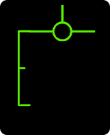
|
8.7° AOA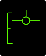
|
8.1° AOA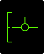
|
7.5° AOA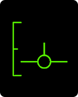
|
6.1° AOA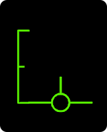
|
Courseline Steering Symbology
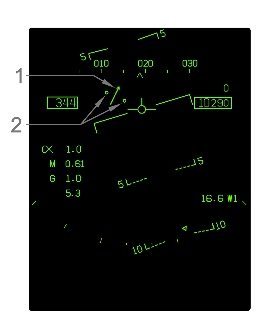
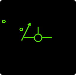
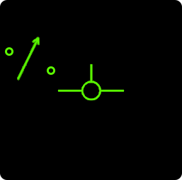
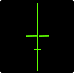
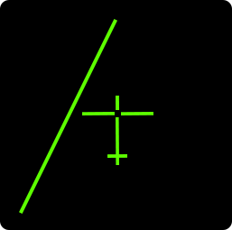
When a courseline is defined for a TACAN/Waypoint with the courseline switch and that point is selected for steering (either TCN or WYPT boxed on the HSI, as appropriate), a course deviation indicator is displayed near the velocity vector. Note that the command heading cue is removed from the heading scale when a courseline is selected.
For details on the courseline steering mode and the cuing on the HSI format, refer to HSI Courseline Steering Cues.
- Course Deviation Arrow - This arrow is positioned relative to the velocity vector to indicate the aircraft's deviation from the courseline. When the arrow is aligned with the velocity vector the aircraft is on course. When the velocity vector is right of the arrow, the aircraft is right of course, and vice-versa. The arrow rotates to indicate the courseline relative to ownship heading.
- Course Deviation Dots - Two dots are displayed on either the left or right side of the velocity vector, along where the arrow moves, to indicate the deviation from the courseline. The outer dot indicates 8° and the inner dot indicates 4°. The arrow does not move past the outer dot, so at deviations more than 8° the arrow will be pinned to the outer dot. Both dots are removed when within 1.25° of course.
| HUD | 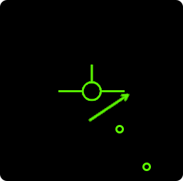
|

|
|
|
|---|---|---|---|---|
| HSI Format | 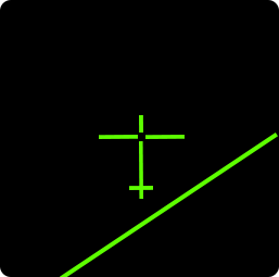
|
|
|

|
| 2° left of course, flying away | On course | 3° right of course, flying toward | 7° right of course, flying toward |
ICLS Steering Symbology
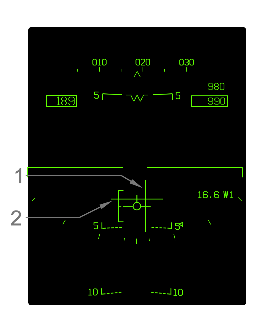
The Instrument Carrier Landing System (ICLS) steering cuing is displayed on the HUD when ICLS is boxed at PB11 on the HSI format.
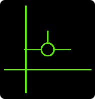
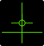
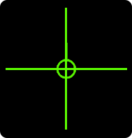
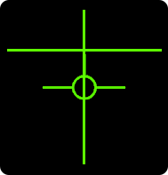
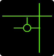
- Localizer Deviation Line - This vertical line is positioned relative to the velocity vector, unless it is outside the HUD field of view; in such case, it is referenced to the waterline "W" symbol. When the line and velocity vector are aligned, the aircraft is on the localizer course. When the velocity vector/waterline is left of the line, the aircraft is left of course and vice-versa. The localizer line represents ±6° of deviation. The line is pinned to its left or right limit at deviation greater than 6°.
- Glideslope Deviation Line - This horizontal line is positioned relative to the velocity vector, unless it is outside the HUD field of view; in such case, it is referenced to the waterline "W" symbol. When the line and velocity vector are aligned, the aircraft is on glideslope. When the velocity vector is below the line, the aircraft is below the the glideslope, and vice-versa. The glideslope line represents ±1.4° of deviation. The line is pinned at its top or bottom limits at deviations greater than 1.4° above or below glideslope.
|
|
|
|
|
| Left of localizer, above glideslope | On localizer, above glideslope | On localizer, on glideslope | On localizer, below glideslope | Right of localizer, below glideslope |
Time on Target (TOT) Symbology
When the time on target (TOT) function is configured on the HSI format, cuing is displayed just under the airspeed box on the HUD so that the TOT can be easily met by adjusting airspeed. Refer to Time on Target (TOT) Function for details on configuring a time on target.
- Current Ground Speed Caret - This caret indicates the current aircraft ground speed relative to the required ground speed cue. When the caret is left of the line, the aircraft is slower than the required groundspeed, and vice-versa. The deflection of the caret is ±60kts; as such, the caret is pinned to the left or right side of the airspeed box when slower or faster than the required groundspeed by 30 knots or more. Note that due to the caret representing ground speed, the change in the ground speed may not be 1:1 with the change in the indicated airspeed above.
- Required Ground Speed Cue - This line indicates the required ground speed relative to the current ground speed caret.
30+ knots slow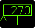
|
15 knots slow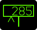
|
On TOT speed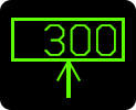
|
15 knots fast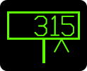
|
30+ knots fast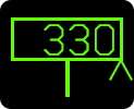
|
Horizontal Situation Indicator (HSI) Format
The Horizontal Situation Indicator (HSI) format is the primary format for navigation. Typically the HSI is displayed on the central MPCD, which has full color capability to display a chart in the background of the top level HSI format.
HOTAS selection of the HSI format is available by pressing the Sensor Control switch aft when the format on the AMPCD cannot accept TDC assignment. This invokes the HSI format on the AMPCD. Additionally, it is possible to swap between the HSI and Situational Awareness (SA) formats on any of the displays. With the TDC already assigned to the HSI or SA, pressing the Sensor Control switch in its direction will cycle between the HSI and SA formats. The SA format is an air-to-air target display with some duplicated HSI symbology. Refer to SA Format.
The HSI format can be displayed on the AMPCD and one (but not both) of the DDIs simultaneously. This behavior is unique to the HSI format.
Top Level HSI Format
The main "top level" HSI format provides a top-down (horizontal) navigation display. The display is normally centered on ownship to provide a 360° view, but can also be forward-focused in the Decentered mode or be freely slewed around using the Map Slew mode. The possible symbols displayed around the compass rose and about the format, which are not described here, are described in HSI Symbols Legend.
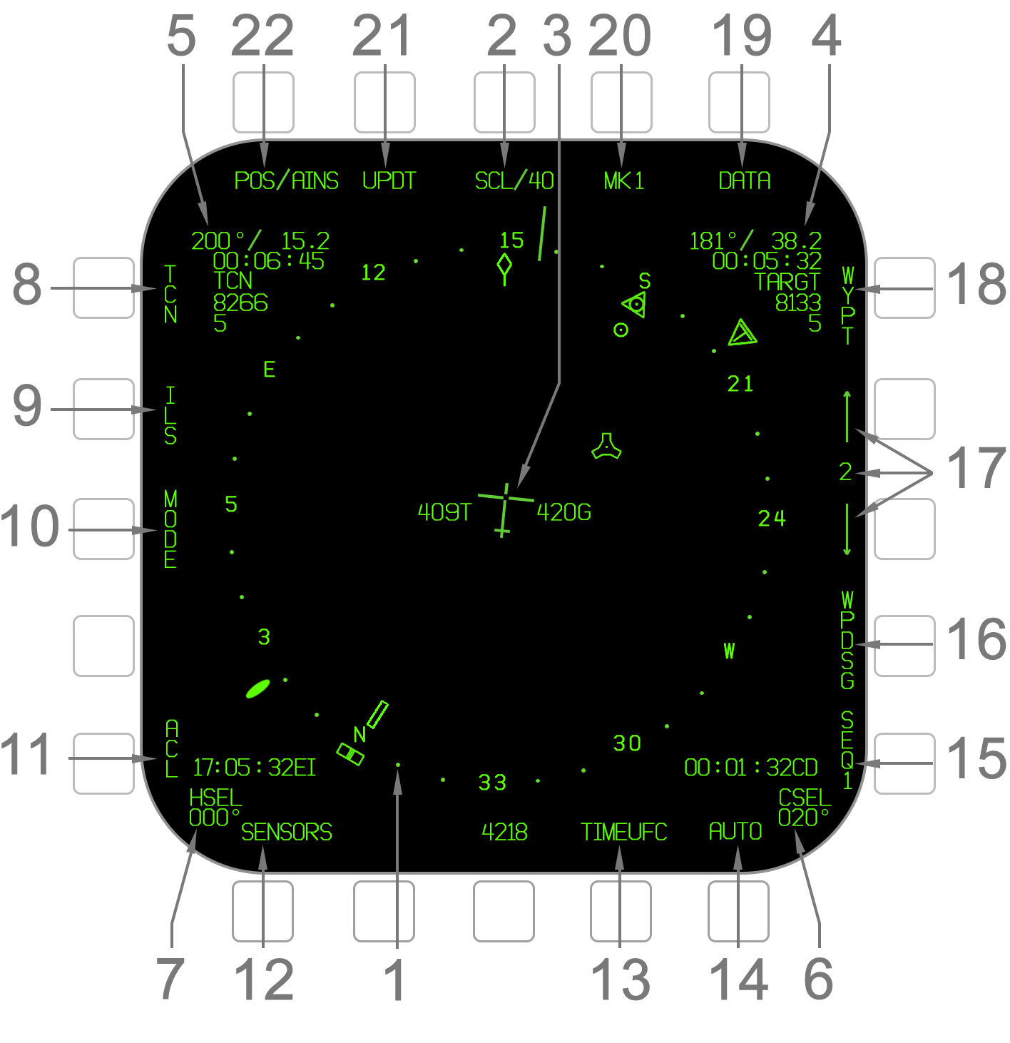
- Compass Rose - The compass rose indicates compass headings around ownship. The numbers indicate abbreviated headings (e.g. 3 for 030°, 24 for 240°) and the dots in between indicate 10° increments. Depending on the format orientation, the compass rose is either oriented to the ownship ground track (T UP and DCTR modes) or to north (N UP mode). There is a variety of symbols displayed along the compass rose. For a description of these refer to HSI Symbols Legend.
- Range Scale - The scale of the HSI format is cycled here through 5, 10, 20, 40, 80, and 160 nautical mile options. The scale is defined as the distance between ownship and the compass rose, so the radius of the format is twice the range scale. When in Decentered (DCTR) mode the range scale value is doubled but it is still measured from ownship to the compass rose.
- Ownship Symbol/Speed - The ownship aircraft position is indicated by this airplane-shaped symbol. True airspeed (T) and groundspeed (G) are displayed on the sides. The symbol is always oriented toward ownship heading (not ground track). This means even in Track Up orientation the ownship symbol may not be pointed directly upward. In some situations there may be cues directly above the true airspeed/groundspeed; see Time on Target Function and Coupled HSI Format Cues.
- Waypoint Data Block - For the selected Waypoint, OAP, O/S, Designation, or Markpoint, data is displayed in the upper-right window (even if is not being steered-to). The information is as follows, from top to bottom:
- Bearing and ground range (XXX°/XX.X)
- Estimated time remaining to arrival (HH:MM:SS)
- Waypoint name; blank if none
- Estimated fuel on arrival (in lbs)
- Distance from suggested descent point based on 3° glidepath to Waypoint elevation
- TACAN Data Block - For the tuned-to TACAN (regardless of whether TCN steering is boxed), data is displayed in the upper-left window. The information is as follows, from top to bottom:
- Bearing and slant range (XXX°/XX.X)
- Estimated time remaining to arrival (HH:MM:SS)
- TACAN station name
- Estimated fuel on arrival (in lbs)
- Distance from suggested descent point based on 3° glidepath to TACAN elevation
- Course Select Course - The course defined for Courseline Steering is indicated here. The course is changed with the Course Select (CSEL) knob above the AMPCD.
- Heading Select Heading - The heading defined for the Heading Select (HSEL) Autopilot mode is indicated here. The heading is changed with the Heading Select (HSEL) knob above the AMPCD.
- TACAN Steering - This toggles the TACAN steering cues on the HUD. It is mutually exclusive with WYPT, TGT, and ACLS steering. TCN is boxed when selected. Refer to Navigational HUD Symbology.
- ICLS Steering - Toggles Instrument Carrier Landing System (ICLS) steering cues on the HUD. ICLS steering can be selected simultaneously with either TCN, WYPT, TGT, or ACLS steering. ILS is boxed when selected. Refer to ICLS Steering HUD Symbology.
- Mode Sublevel - The MODE option invokes the MODE sublevel options. When an option is selected the MODE sublevel is exited. This allows for the format orientation and chart map to be selected. Refer to Format Orientations for the T UP, N UP, and DCTR options.
- T UP - Selects Track Up orientation.
- N UP - Selects North Up orientation.
- DCTR - Selects Decentered orientation.
- MAP - Toggles the chart map in the background. Note that this can only be displayed on the AMPCD.
- ACLS Steering - Toggles Automatic Carrier Landing System (ACLS) steering cues on the HUD. Refer to Automatic Carrier Landing System.
- Sensor Display -
- TIMEUFC - Toggles the TIMEUFC Format on the UFC and allows for the Zulu, elapsed time, and countdown timer cues on the HSI format and HUD to be configured. Refer to TIMEUFC Function.
- Automatic Waypoint Select - When AUTO is selected (boxed), the next Waypoint in sequence will be selected automatically when the aircraft passes the precious one.
- Sequence Select - The SEQ option cycles through the three Waypoint sequences and also toggles a dashed line connecting the waypoints in the sequence. When the option is boxed, the line is displayed. Pressing the option cycles through SEQ1 unboxed → SEQ1 boxed → SEQ2 unboxed → SEQ2 boxed → SEQ3 unboxed → SEQ3 boxed → SEQ1 unboxed, etc.
- Waypoint Designate - The Waypoint Designate option designates the currently selected Waypoint, OAP, or Markpoint as the A/G Designation. WPDSG is only available when a Designation does not already exist. When an OAP is designated via WPDSG, WPDSG changes to O/S. Selecting O/S designates the Offset associated with the OAP.
- Waypoint/Markpoint Selector - The currently selected Waypoint/OAP or Markpoint is indicated here with an arrow to increment/decrement. The selected Waypoint is shown on the main format as a circle, has data displayed in the Waypoint Data Block, and can be steered to on the HUD by boxing the WYPT option. Prior to Waypoint 0 (or after 59), Markpoints 1–9 are available. When a Markpoint is selected, the number is prefixed with an M. Note that the Waypoints may be automatically incremented when AUTO is boxed at PB16. The selected Waypoint and arrows are removed when an A/G Designation exists.
- Waypoint Steering - This toggles the Waypoint steering cues on the HUD. It is mutually exclusive with TCN, TGT, and ACLS steering. WYPT is boxed when selected. Refer to HYPERLINK. WYPT is replaced with TGT (boxed) when an A/G Designation is made, as the aircraft will always be in Designation steering mode when one exists. The Designation can be undesignated by selecting the TGT option.
- Data Sublevel - Invokes the Data sublevel. Refer to DATA Sublevel.
- Markpoint - The Markpoint option designates a new Markpoint at the ownship location or at the current A/G designation, if one exists. The Markpoint saves its location even if the Designation moves or is undesignated. The Markpoint number that will be created upon pressing the MK option is indicated after. Actual Markpoint selection is done at with the Waypoint increment/decrement arrows.
- INS Update - The UPDT option is used to perform an INS position update. Refer to HYPERLINK.
- Position Keeping Source - The INS position keeping source is indicated here. When pressed, the option invokes the Position sublevel where the source can be selected. Refer to HYPERLINK.
HSI Symbols Legend
| Symbol | Name | Description |
|---|---|---|
| Lubberline | The lubberline indicates ownship heading along the compass rose. A "T" is displayed with it when true north reference is selected. | |
| Ground Track Pointer | The diamond-shaped pointer indicates ownship ground track along the compass rose. Except in North Up orientation, it will be fixed at the top of the format. | |
| Heading Bug | This symbol is positioned along the compass rose and indicates the defined Heading Select (HSEL) heading for the HSEL Autopilot mode. | |
| Waypoint/OAP/Markpoint | The position of the selected Waypoint, Offset Aim Point (OAP), or Markpoint is indicated by this circle. | |
| Offset | The position of the Offset (O/S) associated with the selected Offset Aim Point (OAP), if any, is indicated by this +. | |
| Waypoint/Designation Pointer | This triangle rotates along the compass rose and points to the selected Waypoint (or Offset Aim Point, Offset, or Markpoint) or A/G Designation. This is displayed regardless of whether WYPT/OAP/OS/MK steering is selected as long as the Waypoint is selected if there is no Designation. | |
| Waypoint Tail | This filled-in line or "tail" rotates along the compass rose and indicates the reciprocal bearing to the selected Waypoint (or OAP, O/S, etc). In other words it is simply placed at the opposite end of the Waypoint pointer triangle. | |
| A/G Designation | This diamond shape indicates the position of the current A/G Designation, if any. | |
| TACAN | The position of the TACAN station which is tuned to, if any, is indicated by this symbol. | |
| TACAN Pointer | This triangle with a T rotates along the compass rose and points to the TACAN that is tuned to (if any), assuming bearing is received. When bearing is not received but a TACAN is received (range-only), the pointer can be expected to endlessly spin around the compass rose. This can occur with A/A TACANs which only provides range. The pointer is displayed regardless of whether TCN steering is selected, as long as a TACAN is received. | |
| TACAN Tail | This line or "tail" or rotates along the compass rose and indicates the reciprocal bearing to the tuned TACAN. In other words it is simply placed at the opposite end of the TACAN pointer triangle. | |
| ADF Pointer | This "bubble" shape rotates around the compass rose and indicates the Automatic Direction Finder (ADF) bearing whenever the ADF is on. |
Format Orientations
At the MODE option at PB3, the Track Up (T UP), North Up (N UP), and Decentered (DCTR) orientations are selectable. The MODE sublevel exits once any option is selected. Track Up is default-selected.
Track Up (T UP) / North Up (N UP)
The Track Up and North Up orientations are similar. Both are a 360° view centered on the ownship aircraft symbol. In Track Up, the ownship track over the ground (not necessarily ownship heading) is always oriented at the 12:00 position on the format. Note that the ownship symbol is oriented toward heading, not ground track. In North Up, the north direction is oriented at 12:00 regardless of ownship track or heading.
Track Up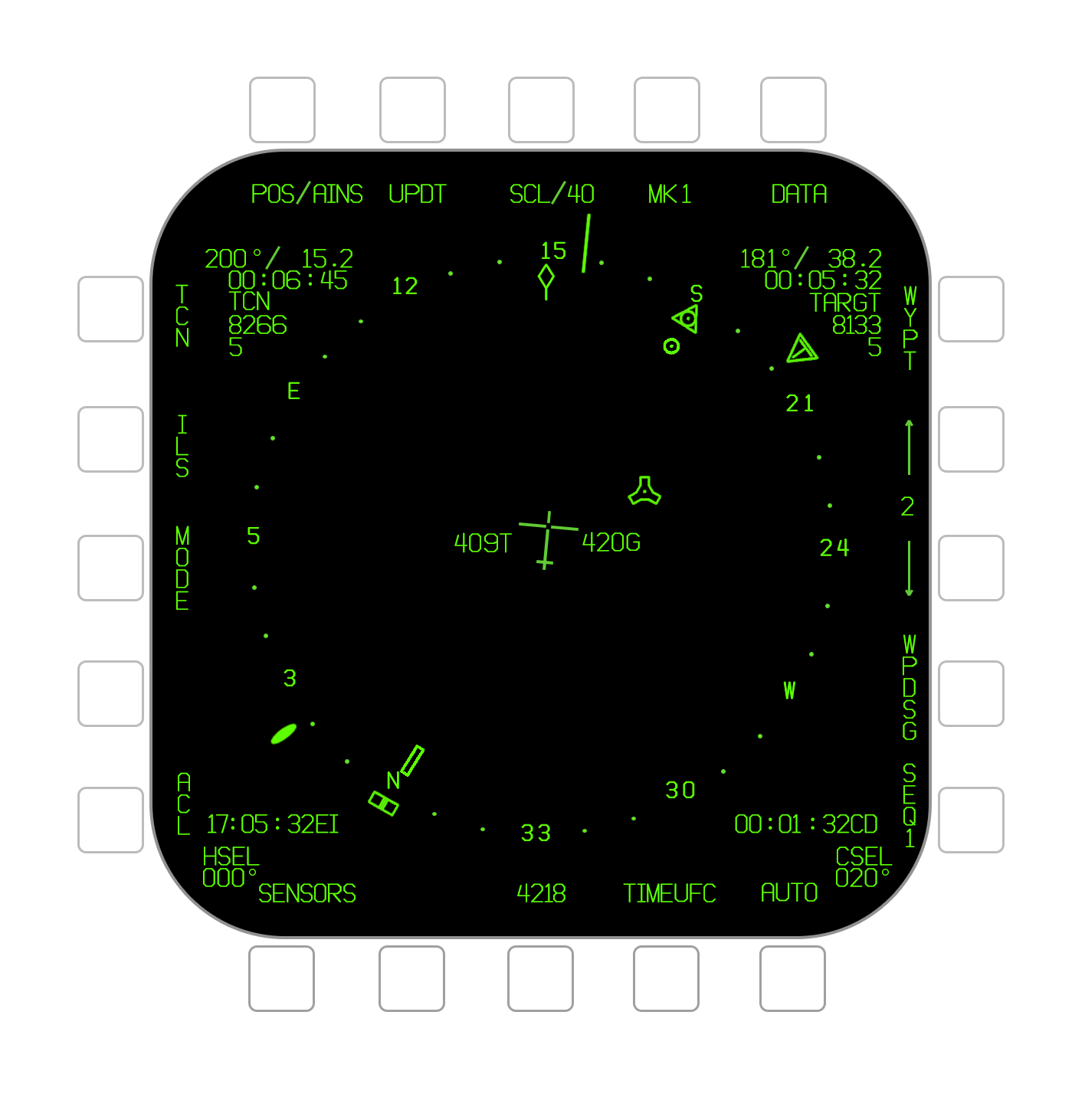
|
North Up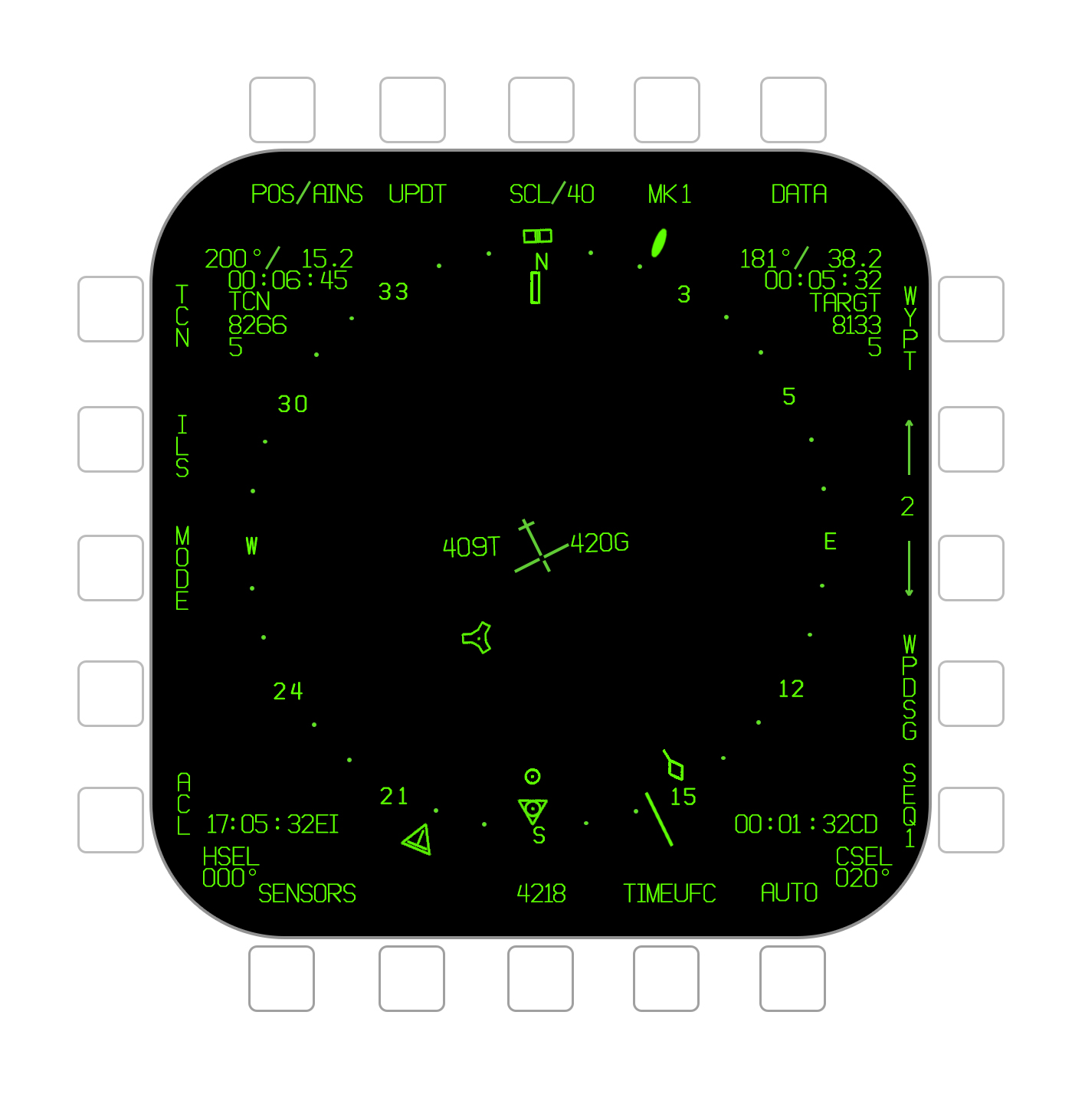
|
Decentered (DCTR)
The Decentered (DCTR) orientation is different from the other orientations in that the HSI is not centered on ownship. When Decentered, ownship is placed at the bottom of the format (and centered horizontally). The HSI only covers 80° total in DCTR and is oriented to track up. The range scale setting is doubled, but is still measured from ownship to the compass rose. The same total area is displayed, with double the distance displayed ahead of ownship as in Track Up or North Up modes. The ability to see farther ahead is the main advantage of the Decentered orientation.
Picture of Decentered.
Map Slew Function (SLEW)
Courseline Steering Cues
The HSI format provides courseline steering cueing for the selected Waypoint or TACAN whenever a course has been defined with the Course Select (CSEL) knob.
- Courseline - A line is drawn through the point for which a course is defined. The arrow on the line indicates the direction of the course, so as to differentiate reciprocal courses.
- Distance from Course - The distance from ownship to the closest point on the courseline is indicated here in hundredths of a nautical mile (X.XX).
Markpoint Creation (MK#) Function
Time Display
The HSI format has two windows for displaying a time value. The time types are Zulu time of day (ZTOD), an elapsed timer (ET), and a countdown (CD). One of these can also be displayed on the HUD. Configuring the time display is done on the UFC; see Time UFC Format.
Picture
- ZTOD Window - The Zulu time of day (ZTOD) can be displayed in this window in the format HH:MM:SS with the suffix EI.
- CD/ET Window - A countdown (CD) or elapsed time (ET) time value can be displayed in this window. Both are in the format MM:SS with the suffix CD or ET.
Time UFC Format
The Time format on the UFC is used to configure the time values displayed on the HSI format and on the HUD. The HUD can display a single one of the three time values. The time value which is last selected is displayed on the HUD.
The format is also used for manually setting the time and date if the real time clock fails.
The Time format is brought up and deselected with the TIMEUFC option (PB17) on the HSI format. TIMEUFC is boxed when the Time format is displayed.
- Date Set - The current date can be entered using the keypad with the SET option (DDMMYY) and then the ENT key.
- Zulu Time of Day - The ZTOD option will toggle display of the Zulu time of day on the HSI format and HUD. Selecting ZTOD also allows for the current ZTOD to be manually set via the keypad by entering the hours, minutes, and seconds (HHMMSS) and then pressing ENT. However, manual ZTOD entry is normally only required if the automatic real time clock (RTC) fails.
- Local Time of Day - The LTOD option allows for the local time of day to be manually set via the keypad by entering the hours, minutes, and seconds (HHMMSS) and then pressing ENT. The LTOD cannot be displayed on the HSI or HUD.
- Count Down - The CD option will toggle display of the countdown timer on the HSI format and HUD. The CD timer will by default start at 06:00. It can be paused and resumed with the ENT key. When selected a new starting point for the countdown can also be entered by entering the minutes and seconds (MMSS) and then pressing ENT. The maximum start value is 59:59.
- Elapsed Timer - The ET option will toggle display of the elapsed timer on the HSI format and HUD. The ET will by default start at 00:00. It can be paused and resumed with the ENT key.
Data Sublevel
The Data sublevel of the HSI format is toggled using the DATA option at PB10. The Data sublevel is organized into four further sublevels. The unique options to those individual sublevels are detailed in the next subsections.
Picture
- Data Sublevel Toggle - The DATA option toggles between the Data sublevel and the top level format.
- Sublevels - The four additional "sub-sublevels" of the main Data sublevel are selected here.
- NAV Check Sublevel - Toggles the NAV Check (NAVCK) sublevel.

