HUD
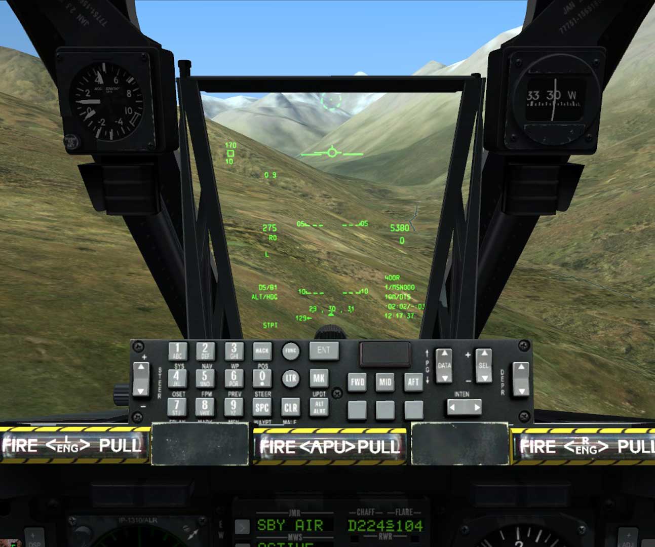
The Heads Up Display (HUD) is one of the most useful systems in the A10 and combines most of the systems in the A10 into one final interface.
Contents
- 1 Modes
- 1.1 Nav Mode
- 1.1.1 Depressable pipper
- 1.1.2 Total Velocity Vector (TVV)
- 1.1.3 G Meter
- 1.1.4 Airspeed
- 1.1.5 Required Airspeed
- 1.1.6 Barometric Altimeter
- 1.1.7 Flight Path Angle
- 1.1.8 Target Designation Cue
- 1.1.9 HUD SOI Marker
- 1.1.10 Heading Tape and Scratchpad
- 1.1.11 Current Sensor Point of Interest (SPI)
- 1.1.12 Radar Altimeter
- 1.1.13 Selected Steerpoint and Steerpoint Name
- 1.1.14 Distance to steerpoint
- 1.1.15 Time To Go to Steerpoint
- 1.1.16 Time
- 1.2 Continuously Computed Impact Point (CCIP)
- 1.3 Continuously Computed Release Point (CCRP)
- 1.4 Continuously Computed Release Point (CCRP) IAM Sub-Mode
- 1.5 GUNS
- 1.6 CCIP Gun Cross
- 1.7 Ammo Type
- 1.8 Air To Air
- 1.1 Nav Mode
Modes
There are 5 main modes of the HUD, some with sub modes. They are:
- NAV - Navigation
- CCIP - Continuously Computed Impact Point
- MAN REL - Manual Release (default)
- 3 / 9 Consent to Release - A hybrid of CCIP and CCRP allowing you to attack as you would in CCIP but pull up out of the attack and release the bomb out of a dive
- 5 Mil Consent to Release - A more accurate version of 3 / 9 requiring tighter release paremeters
- CCRP - Continuously Computed Release Point
- GUNS - Gun usage
- Air To Air - Air To Air gun usage and AIM-9M
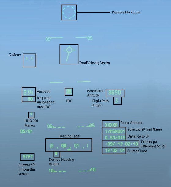
Navigation mode can be thought of as the base mode for the HUD. It strips out the combat system related items and only shows you the items needed for navigation.
It includes the following. Note that items on subsequent modes that are included in Nav mode will only be covered here.
Depressable pipper
Located at the top of the HUD it consists of a dot at the center of a dashed circle. Using the DEPR rocker on the UFC it can be positioned virtually from +10 to -300 mils. It is fixed horizontally on the HUD center line and not wind-corrected. It is generally used as a backup targeting reticle now but before the C upgrade to the A10 was one of the primary aiming systems.
Total Velocity Vector (TVV)
One of the most important parts of the HUD. The TVV is a circle with 3 stationary lines coming out of it from its 9, 12, and 3 o'clock positions representing your aircraft. An additional line extends out of it towards your currently selected steerpoint even if it is off screen. The TVV indicates the flight direction of your aircraft regardless of the direction the aircraft is physically pointed. Modern aircraft like the A10 can fly at high angles of attack where the wings and nose do not point to the exact path of travel. If the pilot places the TVV on the ground and holds it there then eventually the aircraft will fly into that spot.
G Meter
Indicates the current amount of G Load.
Airspeed
The indicated airspeed in knots.
Required Airspeed
The airspeed required to arrive at the selected steerpoint at the assigned Time On Target (ToT)
Barometric Altimeter
The Barometric Altimeter displays the height of the aircraft above mean sea level. It is directly adjusted/calibrated by the knob on the altimeter itself along the front dash to set the local air pressure.
Flight Path Angle
The current flight path angle of the aircraft. Note that this is not the true angle of the nose but rather the angle of travel.
Target Designation Cue
Always displayed when the HUD is SOI this indicator can be slewed within the HUD field of view to select a point on the ground. When the slew is stopped it will try to correlate it with a point in space, if it cannot an X will appear over the box. If it is successful the box will be open and it can be made SPI with TMS Forward Long, then other sensors can be slewed to it with China Hat Forward Long. You can also use it to make a Markpoint with TMS Right Short at the TDC location. It can only select a point up to 13 miles in front of the aircraft and within the HUD field of view.
HUD SOI Marker
This asterisk appears when the HUD is Sensor Of Interest.
Heading Tape and Scratchpad
The heading tape is marked every 5º and has digits labeled every 10º. This areas is also shared by the scratchpad, entering data into the scratchpad will replace the heading tape until it is cleared.
Below it is two lines ( || ) that represent the desired heading to reach the selected steerpoint.
Current Sensor Point of Interest (SPI)
This bottom left field indicates the current SPI. The options can be:
- STPT - Steerpoint
- TGP - Targeting Pod
- MAV - Maverick
- TDC - Target Designation Cue
- TAD - Tactical Awareness Display
Radar Altimeter
The Radar Altimeter senses the height of the aircraft above the surface using RADAR so it works regardless of the barometric altimeter settings. It can read altitudes up to 5000ft and above that will show XXXXR on the HUD.
Selected Steerpoint and Steerpoint Name
Below the Radar Altimeter is the selected steerpoint information including the steerpoint number and its name.
Distance to steerpoint
Next is the distance to the selected steerpoint
Time To Go to Steerpoint
Displayed on the next line is the time of flight at the current speed to the steerpoint. After the slash is the time difference based on the ToT.
Time
The final line contains the current time.
Continuously Computed Impact Point (CCIP)
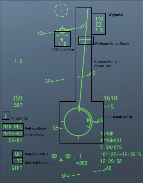
The CCIP HUD mode contains the following.
Consent to Release
Consent to release has 2 options, 3/9 and 5 mil. The difference is the accuracy required for the pipper to pass through the solution cue to release the weapon. The advantage of using CR is that you may designate a target point and then pull-up and release the bomb in a non-diving attack. This gives you the option of wings-level bombing and toss bombing. When changing to the CR mode most of the CCIP HUD stays the same but a few things change. The CCIP Bomb Reticle and the Projected Bomb Impact Line will change to dashed lines. When the pickle is depressed you are designating the target point. The fall line will now resemble a CCRP fall line. You can now pull out of the dive and continue to hold the pickle button while flying the pipper into the release cue. In 5 mil mode you must pass the pipper through the release cue circle, in 3/9 mode it simply must pass through the entire circle but will be less accurate.
CCIP Gun Cross
A wind corrected CCIP gun cross is shown in addition to the CCIP drop interface so that you can follow a bomb drop with guns without having to change modes.
Steerpoint
The steerpoint shown here is not exclusive to CCIP mode however it is the first time that we have seen it. This is showing an open box and the selected steerpoint is off screen by 170 degress above the box and 7.6 miles below the box.
Minimum Range Staple
The Minimum Range Staple indicates the minimum escape range set in the DSMS. This takes into account the minimum release altitude, fuze settings, and height of function for cluster bombs. The CCIP reticle should remain below the MRS at all times in order to drop the weapon above the minimum range.
Projected Bomb Impact Line
The PBIL is displayed as a line directed outward from the center of the CCIP Reticle. The PBIL is a linear prediction of where the CCIP will track across the ground.
CCIP Bomb Reticle
The CCIP Bomb Reticle is a circle with an analog range bar on the inside. An X in the middle indicates the aircraft is below the minimum range altitude.
Time of Fall
This indicates the time of fall for the munition if released at that instant.
Release Mode
The selected release mode. MAN REL (manual release) is selected by default. This can be changed in the IFFCC Test Menu to Consent to Release 3/9 and 5 Mil.
DSMS Profile
The selected weapon profile in the DSMS will be shown here. If a weapon is selected directly it will appear as shown with a M/weapon name as manual profile.
Weapon Status
Indicates weather the weapon systems are in Arm, Train, or Safe mode.
Selected Stations
The stations of the selected weapons are shown here.
Continuously Computed Release Point (CCRP)
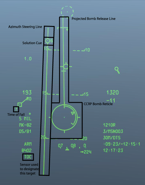
The HUD in CCRP mode is similar to CCIP mode with only a couple differences. The biggest difference is in the operation of weapons release. Note:' This mode applies to Non-INS Guided and unguided weapons in CCRP mode, so it does not apply to the GBU 31/38 or the CBU 103/105.
Azimuth Steering Line
The Azimuth Steering Line can be thought of as a line extending up and out of the target itself. Placing the line in the center of the screen will have the aircraft fly over the target.
Projected Bomb Release Line
Much like the CCIP version this line extends from the top ending in the CCRP Reticle. In CCRP mode line up the PBRL with the ASL as closley as possible in level flight.
Solution Cue
Line up the ASL and PBRL so that the Solution Cue will pass through the CCRP Reticle. Once the countdown next to the Solution Cue reaches 5 second it will begin falling down towards the reticle. As it fall press the pickle button and continue to press it until weapons release.
Current SPI
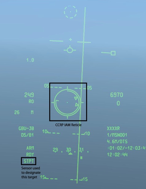
Covered earlier but important to note that in CCRP mode the current SPI decides where the computer will attempt to put the bomb. In this screenshot the target was designated with the TDC. Most commonly this will be done with the TGP, so be sure to set your SPI before attempting to drop a weapon.
Continuously Computed Release Point (CCRP) IAM Sub-Mode
The IAM Sub-mode is almost exactly the same as CCRP except for the CCRP reticle and ASL.
CCRP Reticle
In the IAM sub-mode the PBRL is not present and instead the CCRP Reticle is fixed on the HUD. Line up the CCRP IAM Reticle with the ASL. As you approach the target the minimum and maximum range cues on the inside of the reticle will expand. The final process will have the release cue inside the reticle unwind towards the min and max range cues. While the release cue is between the min and max cues press and hold the pickle button until the weapon releases. Note that this can take up to 3 seconds of pressing the pickle button until it actually leaves the aircraft.
GUNS
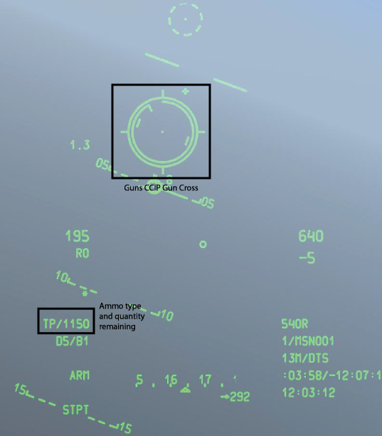
The Guns mode primarily includes a CCIP Gun Cross for the 30mm GAU-8.
CCIP Gun Cross
The CCIP Gun Cross consists of the standard CCIP reticle with a unwinding range cue. The position on of the cue as it unwinds is equivalent in thousands of feet (8'o clock = 8000 feet) in slant range. Below the reticle is the nautical mileage to the impact point. Depending on your target you will need to fire at different ranges.
The dashes to each side of the reticle are wind corrected moving targets leads. They are calibrated for 20 knots of perpendicular motion.
Ammo Type
The ammo type box contains the type of ammo loaded (TP Training Rounds HEI High Explosive rounds CM Combat mix of high explosive and armor piercing) followed by the amount remaining. If it shows XXXX the gun is damaged and inoperable.
Air To Air
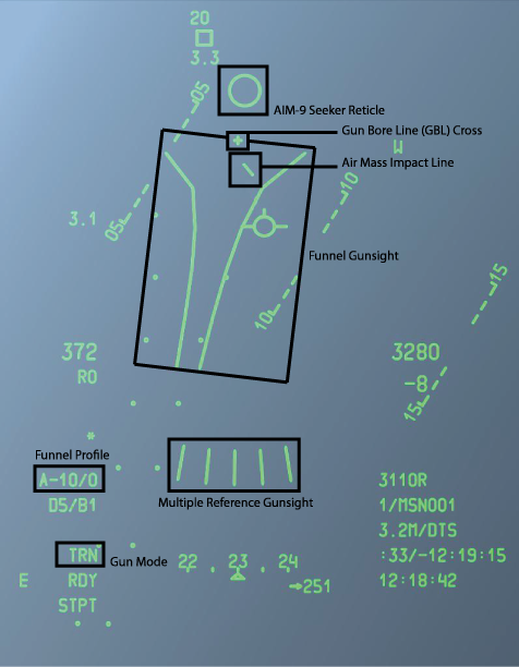
AIM-9 Seeker Reticle
The AIM-9 Seeker is represented by a circle in the upper part of the HUD. It shows where the AIM-9 seeker is currently pointed. It can be controlled with the following controls:

