User:Jak/Sandbox2
Contents
- 1 Navigation Systems
- 1.1 Navigational HUD Symbology
- 1.2 Horizontal Situation Indicator (HSI) Format
- 1.3 Flight Performance Advisory (FPAS) Format
- 1.4 Navigation Equipment
- 1.5 Automatic Flight Control System (AFCS)
- 1.6 Automatic Throttle Control (ATC)
- 1.7 Inertial Navigation System (INS)
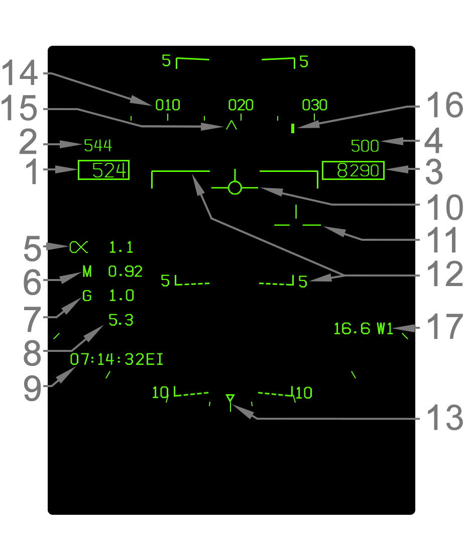
A wide range of information can be displayed on the Head-Up Display (HUD). This section covers basic flight instrumentation and navigation cuing.
The basic flight instrumentation and navigation cues laid out in this section is largely common throughout all master modes and scenarios, except where noted.
- Indicated Airspeed - Indicated airspeed (IAS) in knots is displayed in this box.
- Best Climb Airspeed - When CLIMB is boxed on the FPAS format, the best climb airspeed is displayed above the current airspeed. This is only displayed in NAV master mode.
- Altitude - Altitude is displayed in feet in this box. When the altitude source switch is set to BARO, barometric altitude above mean sea level (MSL) is displayed. If the source is set to RADAR, radar altimeter altitude above ground level (AGL) is displayed if valid. The radar altitude is always suffixed by a letter R. Radar altitude may go invalid due to steep bank angle or being too high above the ground. When the radar altitude is invalid and the source is set to radar, barometric altitude is displayed instead. This condition where radar altitude is selected but barometric altitude is actually being displayed is indicated by a flashing letter B to the right.
- Vertical Speed - Vertical speed in feet per minute (fpm) is displayed directly above the altitude box. A negative value (losing altitude) is prefixed with a minus (-) sign. The vertical speed is only shown in NAV master mode.
- Angle of Attack - Current angle of attack (AOA)/alpha is indicated here next to the Greek alpha symbol. The AOA is blanked when the gear is down and the aircraft is "on speed" (AOA between 6.9° and 9.3°).
- Mach Number - Current speed as a percentage of the speed of sound (Mach number) is indicated here.
- Current G - The current G-force experienced by the aircraft is indicated here.
- Peak G - The highest G-force experienced is indicated here if that peak G-force was more than 4.0G. The peak G is reset when the HUD symbology reject switch is cycled to REJ1 (or REJ2) and back to NORM.
- Time Window - Either the current Zulu time (EI), a countdown timer (CD), or an elapsed time (ET) can be displayed in this area of the HUD. This is set using the TIMEUFC function on the HSI format.
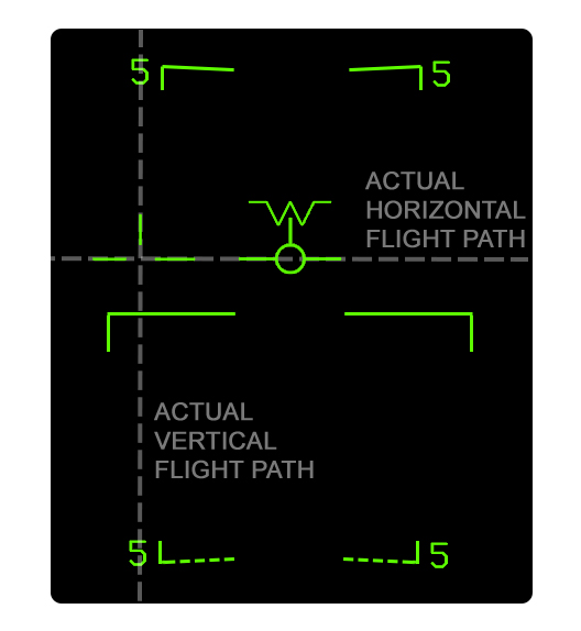
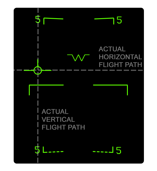
- Velocity Vector - The velocity vector indicates the actual vertical flight path angle and, when uncaged, the horizontal flight path (accounting for wind drift) as well. When the ghost velocity vector is displayed (caged velocity vector operation), then this velocity vector is displayed near the center of the HUD and does not indicate true horizontal drift. Refer to Velocity Vector Operation. The velocity vector flashes if its position is outside the HUD field of view.
- Ghost Velocity Vector - The ghost velocity vector is displayed when the HUD is caged and appears as a segmented version of the velocity vector. Its purpose is to indicate the real horizontal flight path angle of the aircraft with regard to wind drift, while the regular velocity vector remains near the center of the HUD. Refer to Velocity Vector Operation. The ghost velocity vector flashes if its position is outside the HUD field of view.
- Pitch Ladder - The pitch ladder indicates either the true flight path angle (typically) or the nose pitch. Each bar is placed in 5° increments, with angles below the horizon being dashed. For details, refer to Pitch Ladder Behavior. The pitch ladder is always oriented upright relative to the horizon. This is used with the velocity vector, which is always oriented to the aircraft itself, to visualize aircraft roll.
- Bank Angle Scale - Aircraft bank angle is indicated by this scale and the triangle caret that moves along it. The ticks are placed on both the left and right sides at 5°, 15°, 30°, and 45° increments. The triangle is limited just past the final tick at 47°. When bank is greater than 47°, the triangle flashes.
- Heading Scale - The heading scale indicates the current magnetic or true heading of the aircraft in conjunction with the heading caret. The heading scale can be thought of a compass. It is not to scale; in other words the ticks on it are not scaled to the outside world on the HUD. The heading scale is shifted up 1.25° from its position in NAV master mode when in A/G or A/A master mode.
- Heading Caret - This caret simply indicates the current aircraft heading on the heading scale. This does not indicate actual aircraft ground track corrected for wind drift, but only the heading of the nose. When the heading reference is set to true north on the HSI format, the caret becomes a letter "T".
- Command Heading Cue - The command heading cue indicates the commanded heading to steer to the selected waypoint/OAP, offset, markpoint, TACAN, or designation. The command heading cue, although commanding a heading, is corrected for wind drift so that flying the commanded heading will place the aircraft's ground track at the desired point and not necessarily point its nose directly at it. As such, using the command heading cue simply involves steering the aircraft such that the heading cue line and the heading caret are lined up. When steering to an A/G designation, the cue becomes a diamond shape.
- Navigation Range Cue - Range in nautical miles to the selected steer-to point is selected here. This can be a waypoint/offset aimpoint, offset, markpoint, TACAN, or A/G designation. A waypoint/OAP, offset, or markpoint is suffixed by the letter W (waypoint/OAP), O (offset), or M (markpoint) and its number. A TACAN is suffixed by its three-letter identifier. The A/G designation is suffixed by TGT. Range to anything but TACAN is range over the ground. Range to TACAN is slant range.
Pitch Ladder Behavior
The pitch ladder on the HUD is typically in fact a flight path ladder, in that it is positioned relative to the velocity vector. The pitch ladder drifts horizontally with the velocity vector. When the HHD is caged the pitch ladder is aligned with the caged velocity vector, so it remains near the center of the HUD.
Whenever the velocity vector which the pitch ladder is aligned with is outside the HUD field of view (FOV), the ladder shifts to the center of the HUD and is then positioned relative tk the aircraft waterline instead. The waterline is indicated by a "W" symbol whenever the velocity vector is outside the HUD field of view. In this scenario, it only indicates pitch relative to the waterline (nose). Note that when the velocity vector is caged, if only the ghost velocity vector is outside the HUD, no change with the flight path ladder occurs since it is aligned with the caged velocity vector. The caged velocity vector will only escape the HUD FOV in extreme yaw/crosswind scenarios in a bank.
The pitch/flight path ladder contains "rungs" in 5° increments. The horizon itself is indicated by a solid line. Angles above the horizon are solid as well, while angles above are dashed. The rungs are slanted toward the horizon by half the amount of the angle which they represent. For example, the -5° line is slanted 2.5° upward (toward the horizon) and the +10° line is slanted 5° downward.
Caged/Uncaged Velocity Vector Behavior
The velocity vector can either be "caged" or "uncaged". In NAV master mode, this can be toggled with the Cage/Uncage button on the throttle. In A/G master mode, the HUD is always caged. In A/A master mode, the HUD is always uncaged.
When the velocity vector is caged, the "regular" velocity vector is horizontally displayed near the center of the HUD (caged). Navigational cuing is referenced to the caged velocity vector. This makes the HUD easier to read at significant yaw or crosswind components. If the true horizontal flight path angle differs from the ghost velocity vector position by more than 2°, a segmented "ghost" velocity vector is displayed to show the real flight path. Both velocity vectors indicate the real vertical flight path angle of the aircraft.
Note that anytime the aircraft is in a bank, the caged velocity vector may not always be precisely on the center of the HUD, but close to it. This is due to the fact the caged velocity vector has to indicate the true vertical flight path angle while also maintaining the same distance from the ghost velocity vector as the distance between the ghost velocity vector and the aircraft waterline/heading.
When the velocity vector is uncaged, only one "regular" velocity vector is displayed which always indicates the true horizontal (and vertical) flight path angle.
Caged Velocity Vector
|
Uncaged Velocity Vector
|
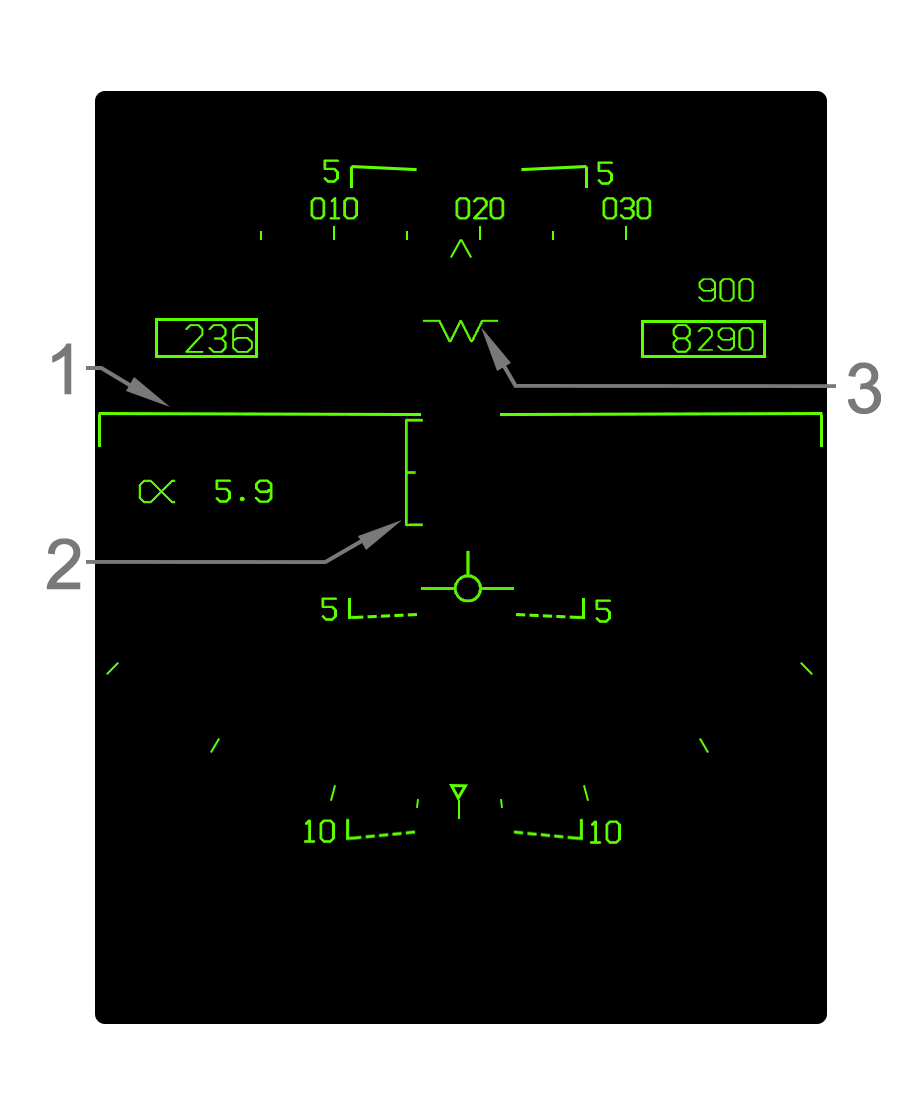
Landing Symbology
When the landing gear is down and locked, NAV master mode is automatically selected and some changes to the HUD are made. In addition to the symbology illustrated, the Mach, G, and peak G numbers are removed. AOA is also removed when the velocity vector is within the AOA bracket.
- Elongated Horizon Line - When the gear is down, the horizon line is elongated as such.
- Angle of Attack Bracket - The angle of attack (AOA) bracket indicates the optimal region of AOA for landing. The bracket is positioned relative to the velocity vector. For details refer to Angle of Attack Bracket. Note that the actual AOA readout on the HUD is blanked when the velocity vector is within the AOA bracket.
- Waterline Symbol The aircraft waterline is indicated by this "W" symbol whenever the gear is down or otherwise whenever the velocity vector is outside the HUD field of view. The waterline is essentially the nose reference of the aircraft; it indicates aircraft pitch rather than the actual vertical flight path angle, which is indicated by the velocity vector. The waterline symbol is coincident with the tops of the airspeed and altitude boxes which can be used for reference since the waterline symbol is not displayed most of the time when the gear is up.
Angle of Attack Bracket
The angle of attack bracket, or "E" bracket, is displayed when the gear is down. It is horizontally aligned with the velocity vector and vertically positioned to visualize AOA relative to the velocity vector. When the HUD is caged it is aligned with the caged velocity vector.
The AOA brackets represents 6.9°–9.3° AOA. The middle mark indicates 8.1°, which is the precise "on speed" AOA for landing. The AOA bracket serves as an easy means of getting "on speed" for landing. The typical technique is to pitch trim the aircraft such that the velocity vector is fixed at the 8.1° mark.
When AOA is between 6.9 and 9.3° (i.e. the velocity vector is inside the E bracket), the AOA number on the HUD is removed as an indicator of being near on speed AOA.
Courseline Steering Symbology
When a courseline is defined with the courseline switch, a course deviation indicator is displayed near the velocity vector. Note that command heading cue is still displayed on the heading scale to indicate the direct course to the steer point.
For details on the courseline steering mode and the cuing on the HSI format, refer to HSI Courseline Steering Cues.
- Course Deviation Arrow - This arrow is positioned relative to the velocity vector to indicate the aircraft's position from the courseline. When the arrow is aligned with the velocity vector the aircraft is on course. When the velocity vector is right of the arrow, the aircraft is right of course, and vice-versa.
- Course Deviation Marks - Two dots are displayed along where the arrow moves to indicate the actual deviation from the courseline. The outer dot indicates 8deg&; and the inner dot indicates 4°&;. The arrow does not move past the outer dot, so at deviations more than 8deg&; the arrow will be pinned to the outer dot.


