| Line 1: | Line 1: | ||
| + | [[File:HUD - NAV Labels.jpeg|526px|center]] | ||
| + | |||
===Tactical Region=== | ===Tactical Region=== | ||
[[File:Attack Format - Tactical Region Labels.jpeg|526px|center]] | [[File:Attack Format - Tactical Region Labels.jpeg|526px|center]] | ||
Revision as of 10:27, 7 May 2021
Tactical Region
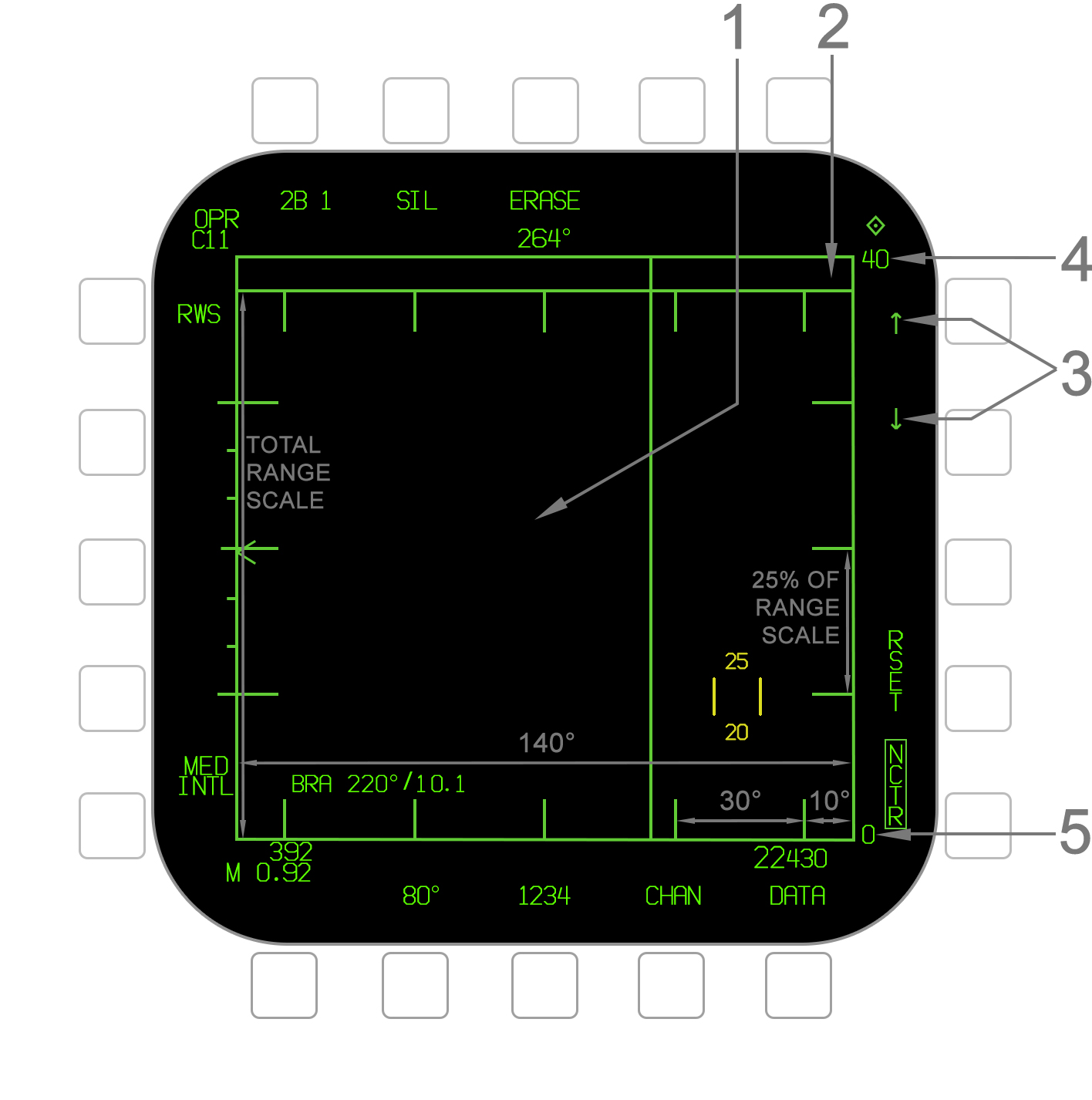
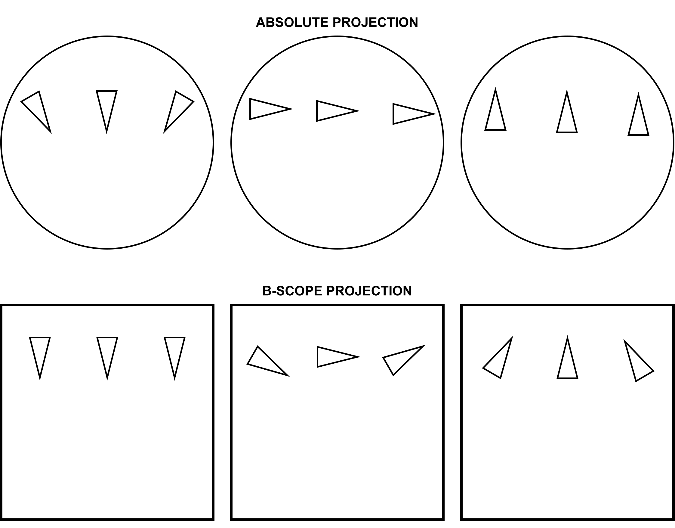
- Tactical Region - The Attack format provides a top-down view of targets. The area in which they are displayed is termed the "tactical region" which is formed by a green outline around the format. The Attack format covers a 140° region (±70°) which is termed the attack region and spans the Radar gimbal limits. The format is a B-scope projection, meaning that the vector stems on HAFU symbols indicate relative aspect to ownship, as opposed to absolute direction. Refer to the image below. The tactical region vertically represents a range scale between 5 and 120 nautical miles, which is adjustable by the pilot or via the ARSA function. Due to the small angle-only trackfile (AOT) zone at the top, the upper 6% of the total range scale is not actually represented. There are scale markings for both azimuth and range as illustrated. Note that the range scale marks are in 20% (instead of 25%) increments when a 5nm or 10nm scale is selected.
- AOT Zone - A separate thin rectanglular area above the main tactical region is termed the angle-only trackfile (AOT) zone or "dugout". This is where angle-only trackfiles are displayed for which the Radar has only determined a valid angle and no range. The AOT zone occupies the top 6% of the overall tactical region.
- Range Scale Arrows - These arrows increment and decrement the maximum range scale. The available ranges are 5, 10, 20, 40, 80, and 160 nautical miles. The range scale wraps around, meaning decrementing at 5nm will select 160 and incrementing at 160 will select 5. Note that Automatic Range Scale Adjustment occurs whenever there is an L&S target, but using the arrows overrides this. The arrows are removed when in STT, EXP, RAID, SCAN RAID, or ACM. In these cases the range cannot be adjusted manually.
- Maximum Range Scale - This value indicates the maximum range from ownship currently being displayed by the tactical region, as set with the range scale arrows or by automatic adjustment. Note that the upper 6% of the range scale is not actually displayed due to the AOT zone occupying the top 6% of the tactical region. For example, if the maximum range scale is 20nm, the maximum displayed range is actually 18.8nm (94% of 20).
- Minimum Range Scale - This value indicates the minimum range from ownship currently represented by the tactical region. This is almost always 0 (i.e. ownship is at the bottom of the format), except in the Expanded (EXP) TWS format, SCAN RAID, and STT RAID modes.
Radar Scan Volume
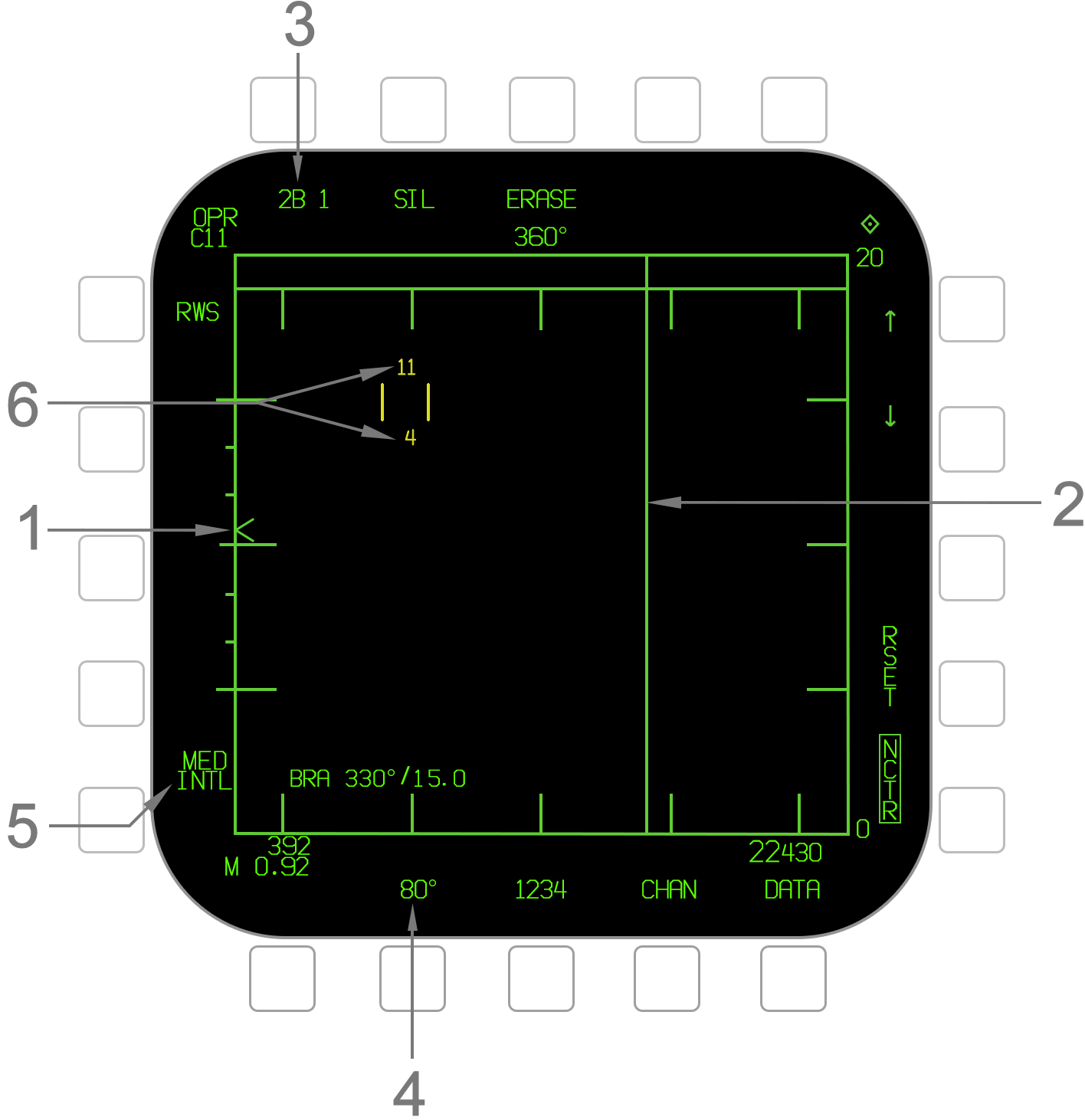
- Elevation Caret - The elevation caret indicates the current vertical angle of the Radar antenna. In the RWS, TWS, and VS search modes the antenna elevation is stabilized to the horizon and so is the caret; i.e. the middle mark on the scale represents the horizon independent of ownship aircraft attitude. In STT or ACM, it indicates the actual vertical angle of the antenna relative to the aircraft body and is affected by pitch. The caret can deflect up to ±60°. Tick marks are placed in 10° increments for the first ±30°.
- B-Sweep Line - The B-sweep line indicates the current horizontal position of the Radar antenna. In the RWS, TWS, and VS search modes, this always indicates the horizontal position relative to the horizon, independent of ownship aircraft attitude. In ACM and STT, the B-sweep indicates the horizontal position relative to the aircraft body and is thus affected by roll.
- Elevation Bar Select - This option cycles through the available elevation bar settings of 1, 2, 4, and 6 bars. The first number indicates the selected bar setting and the second indicates the bar the scan frame is currently on. Note that in TWS, 1 bar is not available.
- Azimuth Width Select - This option cycles the azimuth width setting through 20°, 40°, 60°, 80°, and 140° widths. Note that in TWS the largest available width is limited by the elevation bar setting.
- PRF Select - This option cycles the Radar pulse repetition frequency (PRF) through medium (MED), high (HI), and interleaved (INTL). When INTL is selected, the actual current PRF of MED or HI is displayed below it. When the range scale is set to 5nm, only MED is available. In VS, only HI is available.
- Cursor Altitude Coverage - The Attack format cursor consists of two vertical lines and is slewed with the TDC. Among numerous other functions discussed in subsequent sections, the cursor indicates the vertical scan volume coverage. The maximum and minimum altitudes (MSL) covered by the current scan volume, at the cursor's current position, are indicated in thousands of feet above and below the cursor. These numbers are only displayed when the cursor is in the tactical region (and not in the AOT zone). The maximum/minimum values are 99/-99.
The size of the volume of space which the Radar scans is defined by the scan azimuth width and the elevation bar setting. In the RWS, TWS, and VS modes, the scan elevation and azimuth are stabilized to the horizon, meaning changes to the aircraft's attitude such as rolling or pitching do not affect the orientation of the volume of space covered by the scan. In the ACM modes, these parameters are stabilized to the aircraft body and are thus affected by pitch and roll. In STT, this is inapplicable since the antenna is constantly slaved to a single target.
As described above, the scan azimuth width and elevation bar can be changed by the pilot on the Attack format in RWS, TWS, or VS. In ACM, these properties are fixed to the ACM mode used. In STT, the volume is not applicable since the antenna is slaved to a single target. In RWS, scan volume parameters (and other parameters) are saved to each A/A missile type, allowing for three setting presets in RWS. These presets can be changed; refer to the RWS SET Function.
The total azimuth width/elevation bar coverage is termed the scan volume. A complete set of horizontal sweeps at the set azimuth width for each elevation bar set is termed a single scan frame. A scan frame thus takes more time to complete with a larger scan volume (azimuth width/bar setting). Since the scan volume is defined by angles, the physical space covered is a cone shape and increases as range from ownship increases.
A larger scan volume will provide greater situational awareness as the Radar has the potential to detect more targets. However, a smaller scan volume allows the Radar to complete scan frames in a shorter amount of time, giving it a higher update rate on targets or better trackfile "quality." This is particularly important for AMRAAM missile guidance. The pilot must weigh these factors against the tactical situation.


