Basic Airmanship
The Flying Handbook published in 2016 by the FAA defines Airmanship as, "a broad term that includes a sound knowledge of and experience with the principles of flight, the knowledge, experience, and ability to operate an airplane with competence and precision both on the ground and in the air, and the application of sound judgment that results in optimal operational safety and efficiency." While DCS is a simulation, the accuracy of the flight model means an understanding of aerodynamics and the skills and techniques that make a good airman can be beneficial in helping many beginner sim-pilots over the initial hump. This guide covers the basics of powered, fixed-winged flight, the basic maneuvers that all pilots should know, and a brief introduction to situational awareness and safety.
Contents
- 1 Fundementals of Flight
- 2 Basic Maneuvers
- 3 Situational Awareness & Safety
- 4 What's Next?
- 5 Rotary Flight
Fundementals of Flight
The Four Forces
There are four basic forces that are relevant to flight with heavier than air aircraft. Rotorcraft, such as helicopters, and VSTOL aircraft are also affected by these same four basic forces, but for simplicity and clarity, this section provides details for fixed-wing aircraft only.
Thrust
Forward thrust is generated by the engine of the aircraft, either by the blades of a propeller or by the hot air pushed out the back of a jet engine. Thrust is a function of Newton's Third Law of Motion which explains that every action has an equal and opposite reaction. In the case of jet engines, the hot air produced by the jet engine rushes out the nozzle creating motion in the opposite direction, (and thus pushing the jet) forward.
The thrust generated by the engine only needs to be able to overcome the drag, or aerodynamic friction, of the aircraft.
Lift
Lift is the component of the aerodynamic force that is perpendicular to the flow direction. This force results when the airfoil of the wing causes the surrounding air to be deflected. Again due to Newton's Third Law, this deflection causes a force in the opposite direction, generally upwards opposing gravity.
Aerodynamic lift can be in almost any direction and must simply overcome the weight of the aircraft. During straight and level flight, the lift opposes gravity, but during ascent and descent or during banking, lift occurs at an angle.
Angle of Attack
An important aspect of lift is the angle of attack (AoA, or α), or the angle of between the chord line of an airfoil and the oncoming air. Increases in the angle of attack will result in more lift as the air is deflected through a larger angle and thus the airstream velocity increases up until the critical angle of attack.
The critical angle of attack is the angle of attack which produces the maximum amount of lift. Beyond the critical angle of attack, a stall occurs and the pilot must take action (typically nose down) to regain airspeed and end the stall.
Drag
As an aircraft moves through the air, the air resists the motion of the aircraft in a force called drag. This force is directed along and opposed to the direction of flight. The shape of the aircraft, the viscosity of the air, and the velocity of an aircraft all contribute to the amount of drag encountered during flight.
As an example: A clean F-15C is capable of Mach 2.5 in full afterburner, but only at high altitudes, typically above 35,000 feet. This is due to the viscosity of the air. As the air gets thinner, there is less drag pushing against the aircraft. At low altitudes, a clean F-15C is only capable of Mach 1.2 max. In other words, if you need to go fast, 'remove drag (by going to a higher altitude or dumping stores / fuel, for example).
Weight (Gravity)
The weight of the aircraft is always directed towards the center of the earth. The magnitude of the weight depends on the airframe itself, the amount of fuel, and any payload the aircraft is carrying. This is largely why fuel is referred to in aviation in pounds or kilograms.
Weight presents two major problems for flight. An aircraft must overcome the weight of an object, through a combination of lift and thrust. Additionally, the aircraft must be controllable in flight. Both of these problems involve weight and the center of gravity for the aircraft. As you consume fuel and reduce your payload (drop bombs) you must use trim and other means (fuel transfer) to keep the aircraft balanced for controllable flight.
Effects of the Controls
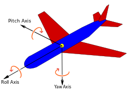
There are three axes of motion that affect every aircraft in flight. Nose left or right movement about an axis that runs up to down, the normal axis, is referred to as yaw. Nose up or down movement along an axis that runs from wing to wing, the lateral axis, is pitch. Finally, rotation that occurs along an axis that runs from nose to tail, the longitudinal axis, is referred to as roll. We can also refer to each of these axes by the motion performed, yaw, pitch, and roll. These three axes are called the Principle Axes of Aircraft and they, with the control surfaces, are a pilot's tools for manipulating the forces of flight. A combination of yaw, pitch and roll is referred to as attitude of flight (or simply attitude) or orientation of the plane in 3D space.
Rudder (Yaw)
The rudder in an aircraft is often described as working similarly to a boat. If you push the left rudder pedal, the aircraft will yaw left, or right if you push the right rudder pedal. Unlike a boat, the rudder is not the primary way to turn left or right. The primary purpose of the rudder is to counteract adverse yaw that occurs while banking (rolling) left or right. This adverse yaw occurs due to extra drag created by the lowered aileron and will cause a banking aircraft's nose to point outward from the direction of a turn. Applying the right amount of rudder during a turn reduces the drag on the aircraft and minimizes the risk of entering a spin.
Ailerons (Roll)
Every fixed-wing aircraft has at least two ailerons, one on each wing. These control surfaces provide the primary way of steering an aircraft. In order to make a turn, a pilot pushes the control stick or rotates the yoke to the left or right. This action causes one aileron to move up while the other moves down, causing the aircraft to rotate about the roll axis. The aircraft, now banking, will turn in the direction of the lower wing.
Elevators (Pitch)
Elevators allow the aircraft to pitch up or down about the pitch axis. The primary purpose of the elevators is in their name, as they help the aircraft to elevate itself into the air. Pulling back on the stick or yoke will cause the aircraft to rotate nose up and ascend. Pushing the stick or yoke in will cause the aircraft to instead rotate nose down and descend. As the aircraft ascends or descends, it loses or gains airspeed. Nose down will cause the aircraft to speed up, while nose up will cause the aircraft to slow down.
Using elevators during a turn can also assist in making a tighter, more rapid turn at a high cost of energy. Note that using elevators during a turn will also involve using more rudder to counteract adverse yaw. We cover this more in the sections under Basic Maneuvers.
Trim
There are situations where keeping the aircraft in the current attitude (combination of yaw, pitch, roll) will require significant pressure on the control stick by the pilot (for example, to avoid smacking into the terrain). As this fatigues your muscles rapidly, we can instead apply trim to the aircraft to avoid having to hold that pressure: we instead 'trim' the control surfaces to such a setting that we no longer have to hold this pressure, but the aircraft instead will hold the pressure - and therefore the attitude - for us!
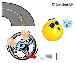
The process of trimming would be similar to a driver of a car driving on a perfectly round (circular) race track. Once he removes his hands from the steering wheel, the car will veer out of control: were he to attach a spring (coil) to his steering wheel, he can now let go as this spring will instead alleviate the pressure of holding the steering wheel in the desired position. Even if he has to make some minute changes to the steering input, he does not have to exert much force / pressure on the steering wheel to make such a change.
Trimming the aircraft can either be done by rotating trim wheels or by operating a trim HAT on your stick, but the process is the virtually the same. We first need to find out where we want the aircraft to go (away from the ground, for example), and maneuver the aircraft into this desired attitude (direction) so that it will go there. Now if we let go of the stick, we will find that the aircraft moves away from this desired attitude, so we apply trim so that is stays (roughly) in our attitude. Trimming is a fine process that takes some time to learn and to get it right, but it is very helpful in all manner of situations: trimming on take-off and landing for example allow you to focus on the situation outside the cockpit and reduce pilot stress.
Flight Instruments
When driving a car a responsible driver will occasionally check his / her gauges on the dashboard to ensure that proper speed is maintained, the engine is not overheating and that there is enough fuel left for the forseeable future. If any of these parameters are out of the desired range (eg fuel is getting low) the driver has to correct accordingly (fill up the tank at a fuel station) to ensure safe travel.
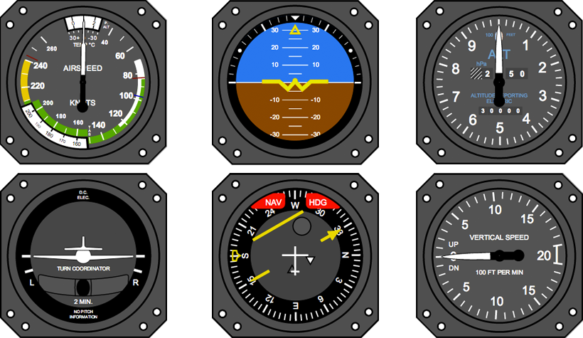
Any aircraft will have similar instrument gauges, but due to the nature of avation and flight in 3D space there are more parameters to monitor and adjust accordingly. For basic flight we monitor the 6 critical flight instruments and their respective parameters at any given stage in flight. Please note that any aircraft will have these instruments, but they may be 'hidden' in display pages or they could be combined together into 1 display (such as the Heads Up Display):
- {top left} The Airspeed Indicator shows you the indicated airspeed of the aircraft
- {top center} The Attitude Director Indicator ('ADI') shows you the attitude of the aircraft, relative to the horizon
- {top right} The Altimeter shows you the altitude of the aircraft
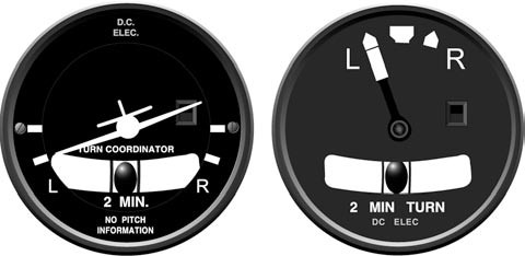
- {bottom left} The Turn And Slip Coordinator shows you the current bank level and slip of the aircraft: this instrument is usually integrated into the Attitude Director Indicator
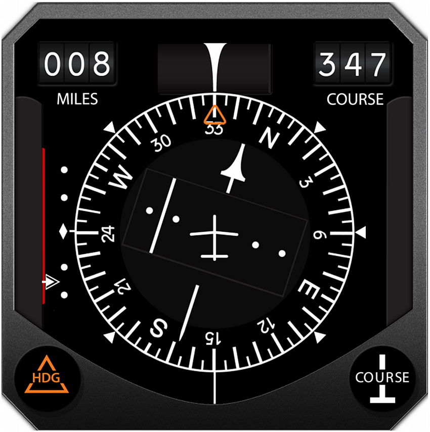
- {bottom center} The Heading Indicator or Horizontal Situation Indicator ('HSI') shows you the current aircraft heading as well as any waypoint headings
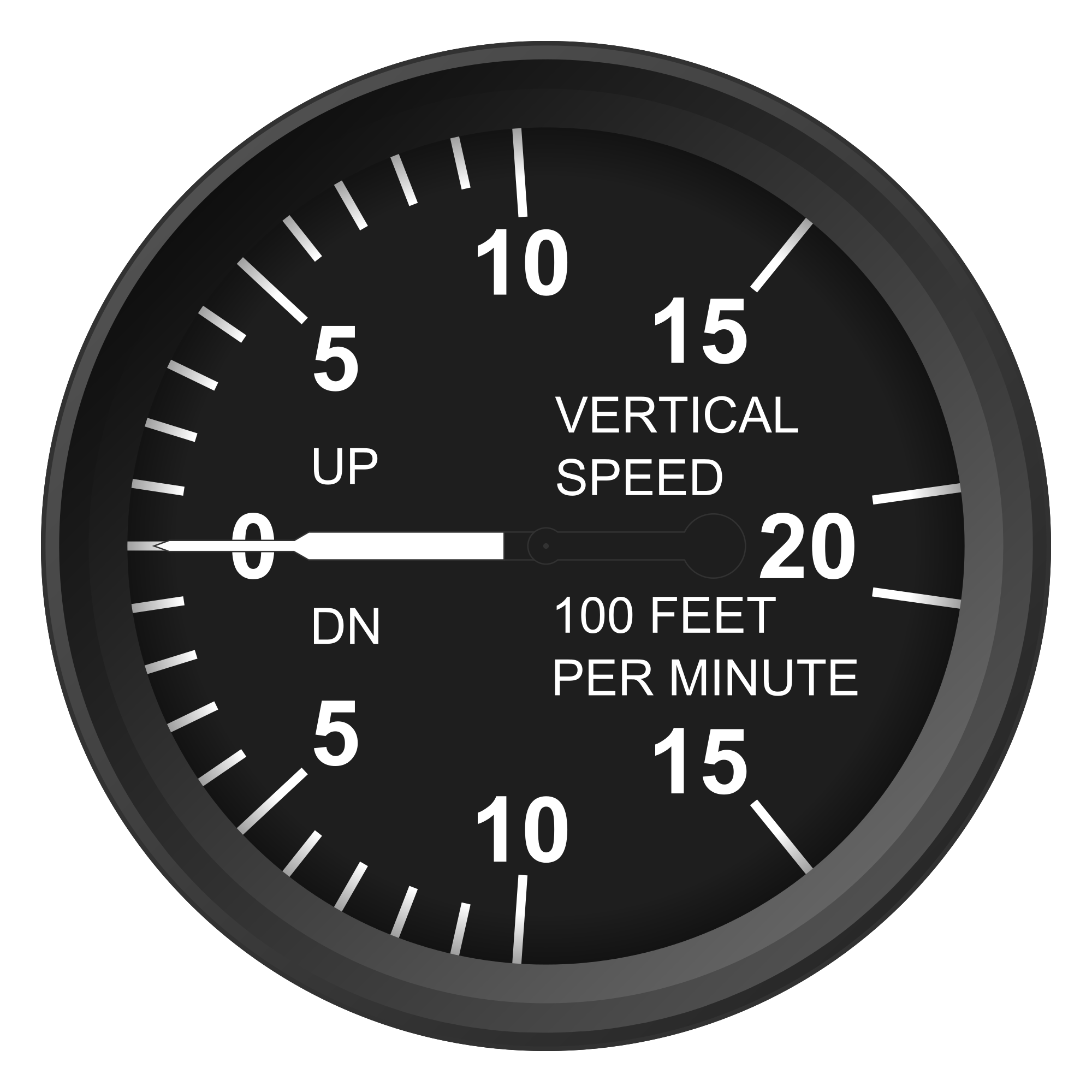
- {bottom right} The Vertical Velocity Indicator ('VVI') shows you your descent / ascent rate
1. Airspeed Indicator
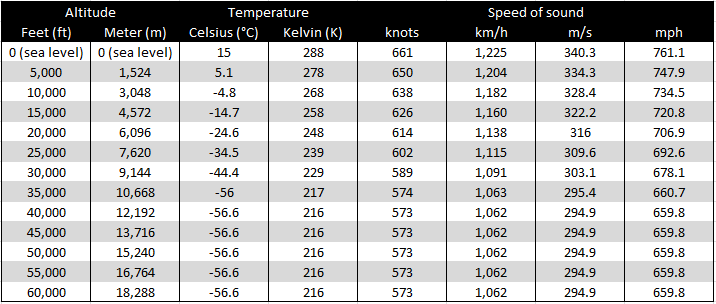
The Airspeed Indicator will tell you the speed that the aircraft is currently cruising at, typically in knots (1 kt/s = 1.85 km/h = 1.15 m/h), though Russian aircraft typically will show the speed in kilometers per hour. Aircraft capable of breaking the sound barrier will typically have an inner gauge or display within the Airspeed Indicator to diplay the mach number (once they have exceeded the speed of sound), but it can also be a seperate indicator of its own. Please note that the speed of sound to be exceeded - and therefore the mach number - varies per medium and per combination of pressure. Although it is unlikely that you are going to encounter any medium other than air, the pressure differentation is dependent on both the temperature and altitude that the aircraft is currently in. Please reference the table for more details.
The airspeed indicator can also display safe operating speeds for the flaps and slats on the wings or the gear, though this is uncommon to be displayed on military jets. In any case, these indicators do not follow any standards (color markings, speed ranges) and thus it would be recommended to check the aircraft operations manual / guide to verify the markings on the airspeed indicator.
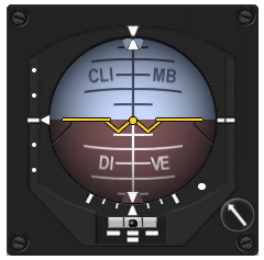
2. Attitude Director Indicator (ADI)
The Attitude Director Indicator (ADI for short) shows you the attitude that the aircraft is currently in, in relation to the horizon: hence why this instrument presents an artificial horizon. This instrument consists of a ball like shape in the center of the instrument (circle in 2D) that is half painted brown on the bottom to represent the ground (labelled DIVE) and half painted white to represent the sky (labelled CLIMB) that together represent the artificial horizon. The fixed symbol in middle, looking a like a yellow W with extended horizontal symbols represents the aircraft.
To display pitch on the ADI ball it pitches vertically: if you were to ascend the aircraft = pitch the nose (also called 'to pull up') into the sky, the ADI ball is going to roll backward and the yellow W is thus going to move up into the white sky (into the CLIMB half, because your aircraft will climb in altitude). Conversely, if you are to descend the aircraft = pitch the nose down, the ADI ball rolls forward and the yellow W is going to move down into the brown dirt (into the DIVE half, because your aircraft will dive down in altitude). The black horizontal bars (short and wide ones) are the degrees of pitch: the short bars represented 5 degrees of pitch (up / down), whilst the wider bars represent 10 degrees of pitch (up / down).
To display roll on the ADI ball it rotates horizontally: if your roll right the ball will show that you are now in a right bank by rolling the ball a bit to the right. Similarly, if you are to roll left from level flight the ball will roll to the right to show you are now in a left bank. The arrows located at the top and bottom of the ADI ball will show the level of bank with the appropriate bank lines on the edge of the ADI (sandwidged between the ADI ball and the slip indicator, the white lines on the bottom) which represent varying levels of bank: when the set of arrows on this edge and the arrows on the ADI ball match up your are in wings level flight (you could be climbing or descending, however).
Some ADI also feature a turn and slip indicator integrated, as is the case in the ADI displayed here. The white bar with the black dot underneath it shows the current turn of the aircraft. If the dot is centered there is no turn going on, whilst if the dot is somewhere (left or right from the center position) in between the center position or all the way maxxed to the left or right, then the aircraft is turning in that respective direction.
Lastly, the dial (with the white arrow on it) can be used to uncage or adjust the ADI vertically if necessary: often this is something done on startup or prior to takeoff to ensure that the ADI is functioning and finely adjusted to match the aircraft setup.
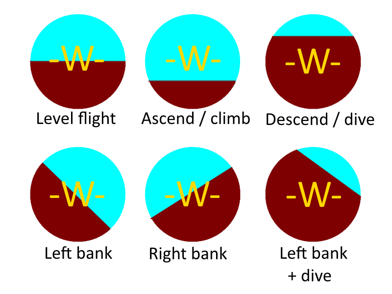
Please consult the simplistic figure below to get a better idea of how the ADI will represent varying flight attitudes.
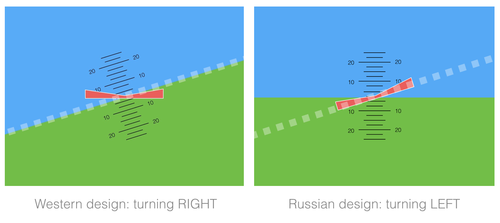
Please note that in Western aircraft when the airplanes rolls the ADI ball rolls with it, ergo the ground moves with the plane symbol (the -W-) being fixed in place. In Russian aircraft the ground is fixed, as instead the plane indicator will roll. Although this yields the same approximate end result on your ADI, the movement to get there is directly opposite between the 2 types of instruments. To avoid mixing them up (and potentially crashing), always remember to look at the (static) relation between the plane (the -W-) and the artifical horizon: Do NOT look for the movement that the ADI (or the artificial horizon) makes. A right turn on a western instrument looks similar to a left turn on a Russian instrument. Both diagrams contain a similarly looking “axis”, but convey opposite information!
3. Altimeter
The altimeter on an aircraft displays the current altitude or height that the aircraft is at. Although typically in 1000's of feet (1 meter = 3.28 feet) for Western aircraft, the Russian aircraft typically display the altitude in 100's of meters; all depending on the type of aircraft and altimeter type of course.
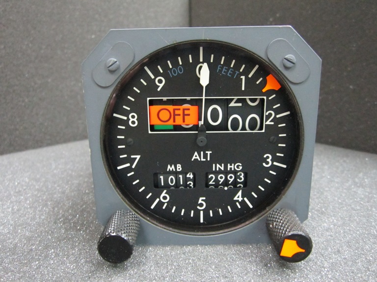
Some altimeters, like the example one shown here, may incorporate a digital (numerical) readout of the altitude rather than requiring the pilot to do this him/herself. This type of numerical display typically has some extra digits in front to display higher altitudes: our altimeter has an additional 2 digits (with the 'OFF' label currently above it to indicate those digits are not in operation) to supplement the 3 digit display so that it can display altitudes with 5 digits (or up to 99,999 feet). Please note that the outer analog display is measured in 100's of feets as indicated by the little subtext.
On any given altimeter you may also find a number of dials present to alter various settings, though typically you may only find 1 dial to set the altimeter pressure. As explained in the previous chapter about the airspeed indicator the altitude, temperature and pressure are linked together: we can thus set the altimeter to read the correct value of the airfield by setting the pressure (given that the temperature is often relatively constant). This is what the two other numerical displays are for: the airport will often calculate and give out the pressure at the airfield so that your altimeter reads correctly.
This pressure at any observation point (airfield/port/oil rig) is called the QFE and can either be measured in milliBars (MB) for European folk or in inches of mercury (inHG). To know which is which refer to the format in which the observation point gives it to you: if it is a decimal value (29.78) it is in inches of mercury whilst if it is somewhere in the thousands (1125) it will be in millibars. Note that although setting the altitude at 0 feet prior to takeoff might seem like a smart move (as this is your reference ground) this brings up problems when the airfield is at an elevation: the altimeter can typically not display negative altitudes and going below 0 feet / meter on your altimeter can have some interesting if not bad results.
The other indicator we have on this altimeter as shown here is an adjustment dial for the low-altitude warning, which can be adjusted to a desired value (by twisting the knob) to ensure that the pilot does not go under this altitude value in flight (goes too low). Some aircraft will feature a warning light on the altimeter itself if this value is exceeded: other aircraft may instead show a warning on the HUD (or elsewhere) or sound an audible tone in the cockpit.
4. Turn and Slip Indicator
The Turn and Slip Indicator in an aircraft is used to monitor the rotation that the aircraft is making, as well as provide a backup to the Attitude Director Indicator regarding aircraft bank (depending on the Turn and Slip Indicator type). The slip indicator (the airplane or the needle) specifically can be used to make a standard rate turn at 3 degrees per second (complete turn 360 degrees at 2 minutes), eg a standard size turn, by lining up the markers to the indicator (either the plane that rotates or the needle that pivots). In faster airplanes this may be replaced wit a half standard rate turn indication, for a 1 minute turn, while conversely in slower aircraft the indications may be fore for 4 minute (2 standard rate) turn.
As explained before, the turn indicator which represents the yaw (or rudder turn) of the aircraft is often integrated with the ADI in military jets, foregoing the turn and slip indicator entirely (as the ADI already provides this information is a more detailed format); for redundancy there will instead be a backup ADI installed. The turn indicator itself (the black indicator in the white bar) works by representing the turn direction: if the indicator is centered, there is no ongoing turn at the moment, where as a deviation to the left or right indicates a turn and the amount of turn in that direction.
5. Heading / Horizontal Situation Indicator (HSI)
The Horizontal Situation Indicator (HSI, heading indicator) shows the current (magnetic) heading of the aircraft on a top down overview display indicator. Typically the airplane will be fixed (sometimes with an indicator on top as well) and the heading disk will rotate to indicate the current heading in degrees: this may be fed from a magnetic compass, board computer that computes the true North, a gyroscope a combination or something else entirely.
The HSI displayed here also has the ability to display range, heading, and course information as well as the standard heading information. As you can see, the current heading we are flying is 33 or 330 degrees, which is approximately North-West-North: this currently matches the desired heading set on the HSI as indicated by the orange triangle symbology. This allows us to set a heading we want to fly and simply match up the lines to fly in that direction.
This HSI is also equipped with a course deviation display indicator, which is the broken up arrow in the center (around the airplane heading symbology). The HSI can be set like the heading indicator to be used for longer range desired heading tracking, but typically it is controlled by selected a desired waypoint or electronic ground station (such as a runway with a landing system) that it will then point to. Rather than only displaying heading information, this bar can move (as evident by the dotted icons) and can thus also display if the position of the aircraft is off from the selected course. This makes it ideal for navigating to the aformentioned ground stations, especially in bad weather or visibility. Our HSI shown also displays the range to this selected (way)point / station.
6. Vertical Velocity Indicator (VVI)
Last but certainly not least, we have our Vertical Velocity Indicator (or VVI) that displays the current climb / dive rate that the aircraft attains. Although the usefulness of this instrument may not be directly evident, there often is a discrepancy between the actual sink (dive) rate and the one that the pilot predicts. Even though you might be performing level flight, if the aircraft is significantly heavy there might be some sinkrate (dive) occuring whilst the pilot is unaware, which will become a problem over time. It is therefore wise to assure every now and then that the VVI is reading as desired, and otherwise adjust the flight attitude accordingly.
The VVI also proves its worth on takeoff and landing legs, as it is then even more crucial to closely monitor the vertical velocity to ensure that you are respectively having a proper climb out after takeoff whilst attaining enough altitude or to ensure that you do not smack the aircraft into the runway (as most aircraft can not handle such stress / forces), but instead flare before touchdown: reducing the vertical velocity to almost 0 when touching down to avoid breaking the landing gear or the aircraft.
Energy
The concept of energy within the aviation domain refers to the amount of current / kinetic and potential energy any given aircraft can exert at that moment: this is important because maneuvers with the aircraft cost energy, with losing most if not all your energy leading to certain doom. For example, making a hard turn whilst already at a slow speed will siphon / bleed off your few remaining units of energy, leading you to lose your remaining lift and stall (into the ground).
It is therefore important to try and conserve energy as much as possible when flying; however, this is certainly not about going slow! The main idea behind energy conservation in aviation is that you do not do excessive maneuvers or perform such maneuvers in a way that causes rapid energy loss. Rather,
Basic Maneuvers
There are four basic flight maneuvers that serve as the basis for all flight. Understanding these are a prerequisite for learning the Basic Fighter Maneuvers and Advanced Combat Maneuvering that every combat pilot needs.
Straight and Level Flight
Coordinated Turns
Climbs
Descents
Situational Awareness & Safety
As sim pilots, we have a lot of luxury of being able to not pay a dire price for our mistakes. Situational Awareness, or SA, and some basic safety is still necessary in order to both be an effective combat pilot and prevent accidental collisions and other things that may frustrate ourselves or other pilots online. More importantly, good Situational Awareness is a life or death skill for every combat pilot. Good Situational Awareness often separates the average combat pilots from the great combat pilots.
Situational Awareness
At an academic level, a pilot's Situational Awareness needs to contain at least four intertwined elements:
- Information from the environment. This can be visual, from sensors, or via communication.
- Integration of that information from all sources to create a mental picture of the situation.
- Using that mental picture to direct further exploration of the environment.
- In order to anticipate future events.
Unfortunately, it's impossible to become an expert at Situational Awareness (SA) by just reading about it, however, these tips should help you build good habits that provide a good foundation for you to build your skills.
- Keep your head out of the cockpit. Every second you are focused on a gauge, screen, or switch is another second that someone can sneak up on you and get a shot off.
- Scan your surroundings constantly. Use your sensors to help focus your scanning, but don't rely too heavily on them. Your sensors are not perfect, and a good bandit can and will sneak up on you.
- Look up and down! You are in a three-dimensional environment. The bandit who wants to kill you may be above or below you.
- Communicate frequently with AWACS. They generally can see much further and clearer than you can. Again, do not rely too heavily on this information.
- When engaged, keep sight of your target but be aware of your surroundings. In other words, do not fixate on your target, but know where he is, always.
- Flying with a buddy or buddies is a good way to maximize SA as your buddy may pick up threats you glanced over or threats you were not able to see in the first place. This is particularly helpful for aircraft that have poor (rearward) visibility, such as the KA-50, Mig-21 or F-5E. In the undesired situation that you are engaged with a bandit, flying with a buddy also helps you to get an advantage on your adversary.
Situational Awareness is one of the harder skills to learn for new pilots, and especially sim pilots since our field of view is generally smaller than real life. Ultimately, practice and don't give up, and over time you will master this essential skill.
Safety
Accidents happen, and with Hoggit, they can often be funny and almost welcome. Frequent accidents from the same individual are often frustrating and unwelcome. Situational Awareness on the ground is as important as it is in the air. Here are a few rules of thumb to avoid frustrating your fellow sim pilots.
- Don't follow too closely behind other players you aren't in communication with. You never know when they will make a mistake themselves leading you to crash into them.
- Follow the server's rules for announcing your taxi and take-off. Often this is in the form of either text, over voice comms, or both. Don't rely on the in-game ATC to handle taxi and take-off.
- Perform aerobatics offset from the runway, or in the server's designated zone.
- When an accident does occur, apologize and learn from it. If it's not your fault remember that next time it could be your fault.
What's Next?
- Check out an airplane guide.
- Read up on Multiplayer.
Rotary Flight
Basic Principles
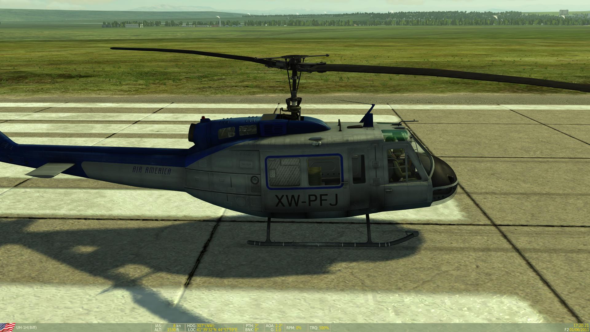
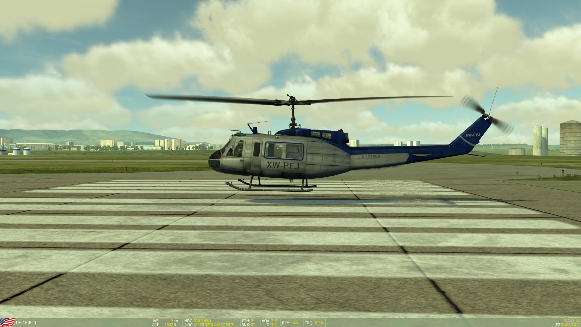
While conventional fixed wing aircraft gain their lift by means of air moving over a surface at high speed due to the forward momentum generated by engines, Rotary aircraft gain their lift by rotating wings at extremely high speed, this provides certain advantages and disadvantages over Fixed Wing aircraft and a variety of phenomena which can ultimately lead to the destruction of the aircraft if not understood properly.
While conventional aircraft will have their engines directly providing thrust for forward momentum, a helicopter uses Turboshaft or Piston Engines to drive a gearbox which will in turn drive the main and tail rotors, much like propeller driven planes. In all but the most basic helicopters, Rotor RPM (or Nr) is governed automatically to remain within an optimum range and does not require manual throttle adjustment unless in an emergency. To control the direction of the aircraft, three main controls are used.
When running at optimum RPM, the rotor blades are spinning so fast they from a ‘disk’ of aerodynamic madness, from this point a lot of reference will be made to the ‘disk’; the collective aerodynamic force off all the blades at once.
- The Cyclic
- The cyclic is located in between the pilot’s legs and is much like the stick/yoke of planes, this controls pitch and roll. Moving the cyclic forward pitches down, back pitches up, left rolls left and right rolls right. This is similar to a plane but understanding the effect of these inputs on the aircraft and how they differ from planes is paramount to understanding how to fly rotorcraft. In short the cyclic changes the pitch angle of the blades cyclically, so that while some of the blades are pitching down on one side of the aircraft, others are pitching up.
- The Collective
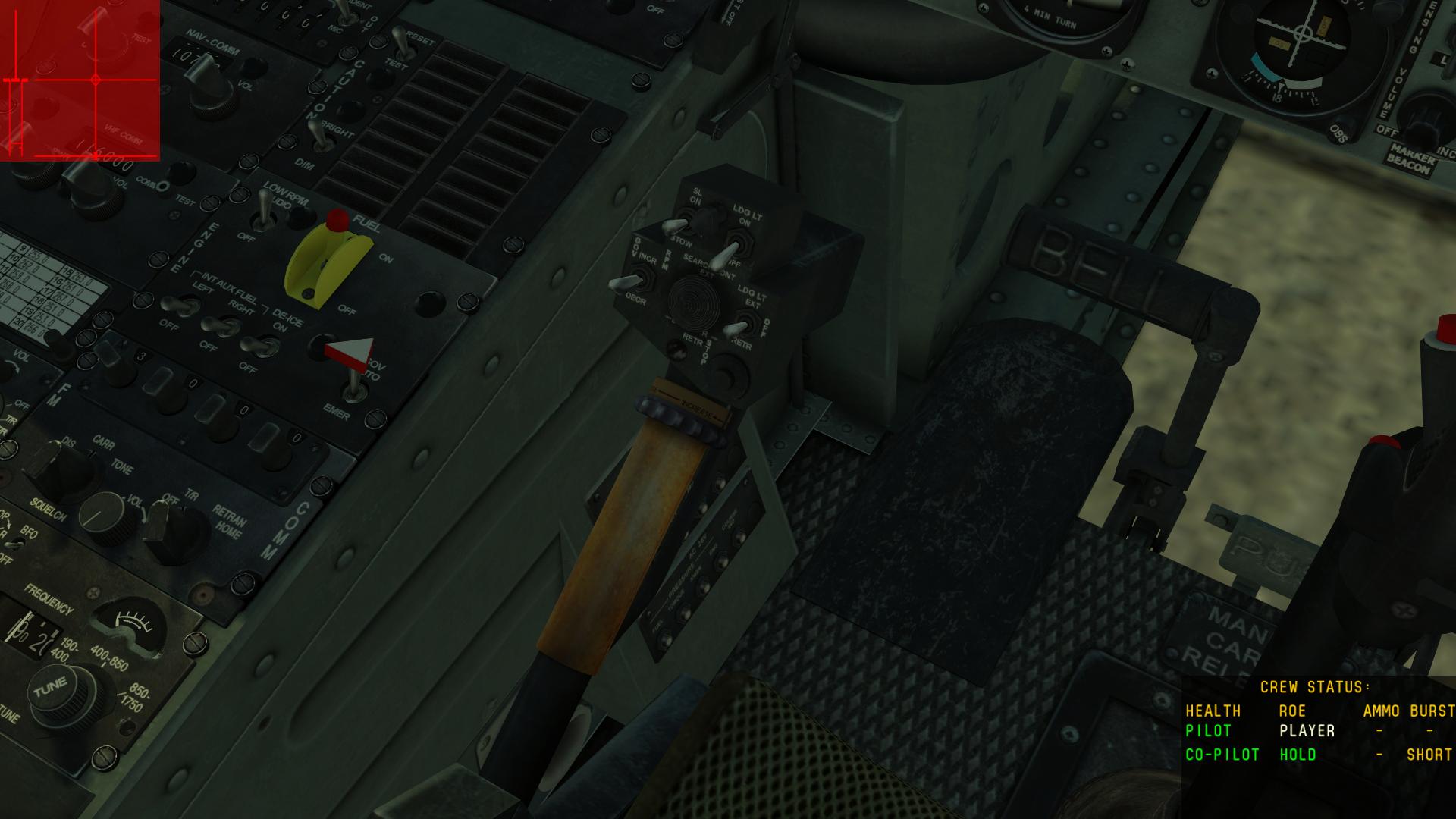
- This lever located to the left of the pilot will increase the pitch of the blades collectively. This means that when you raise the collective, it inputs greater pitch on all the blades at the same time, making you go higher or lower. This lever is intrinsically connected to the power output of the engines more so than the other two controls and the more lever you pull, the more Torque is applied by the engines to the Main Rotor Gearbox. As such this lever is also used as a power lever, allowing you to fly faster in the cruise and the ability to hover due to the unique nature of a helicopter’s power demand curve.
- Anti-Torque Pedals
- Also referred to as Yaw or Rudder pedals, these will adjust the helicopters movement in a lateral sense and also balance the aircraft during turns, much like a plane. Where these differ in helicopters is that due to the nature of having something very large and spinning attached to the airframe, this makes the rest of the aircraft want to spin in the opposite direction to the main rotor, therefore an opposing force is required to maintain stability. The pedals adjust the collective pitch of the tail rotor providing lateral thrust to counteract the rotating forces enacted on the airframe by the main rotor.
- Controls in Harmony
- Successful helicopter flight is achieved by managing all three controls at once to achieve the desired direction of flight, this takes practice and patience. Real helicopter pilots will spend hours attempting to hover before it becomes a muscle memory, and training usually entails getting to grips with one control at a time while an instructor handles the other two before slowly combining all the controls together.
Hovering
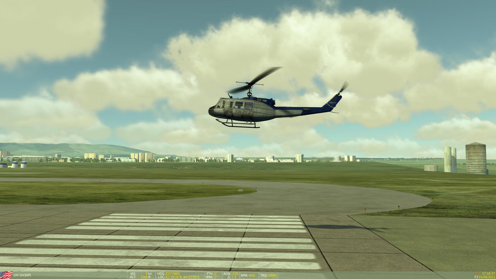
Hovering is one of the more difficult flight regimes to master in rotary aircraft. To be able to maintain a stable hover requires constant correction of all controls, the aircraft will oscilate in all axis and over-correcting is the most common problem when learning. It is recommended when beginning to learn to hover to take off slowly, applying collective gradually until a yaw motion is observed, then correcting the yaw with the appropriate pedal before continuing to slowly feed in the power. Once airborne the most consuming control inputs will be via the cyclic, care must be taken to make small corrections to avoid pilot induced oscillations. It is important to try and focus on a distant reference point such as a tree or building to help to recognise the movement of the aircraft anf the appropriate correction to make. Focusing close by such as the ground directly in front of you will make each small movement the helicopter makes seem greater than it is and leads to overcontrolling. It can take real pilots a number of hours before they are able to maintain a stable hover, much like learning to perform air-to-air refuelling in the fixed wing modules, learning to hover will take practice and patience. It is recommended to learn how to fly the aircraft straight and level to gain an understanding of the interaction and effect each control input has on the others in order to better understand the principles of hovering.
- In Ground Effect Hover (IGE)
- Ground effect for helicopters is much like the ground effect for planes, when close to the ground there will be a 'cushion' of air underneath the helicopter caused by the induced downwash of the rotors. Sitting on this cushion will use less power while hovering although it can have a mild turbulence effect on the aircraft and provides resistance when descending through it to land. When transitioning from the hover IGE to forward flight, the helicopter can be felt to 'fall off' the ground cushion as you become too fast to generate the ground effect, more power will need to be applied as you leave the ground effect to avoid bumping the aircraft off the ground.
- Out of Ground Effect Hover (OGE)
- Hovering out of ground effect is any hover regime not benefitting from the ground cushion generated close to the ground. More power will be required as there is no performance bonus to hovering purely based on induced airflow through the disk.
Effective Translational Lift (ETL)
When transitioning from the hover to forward flight the rotor blades become more efficient as they gain the lift from relative forward momentum. The point at which this occurs differs marginally between aircraft but is generally felt between 20-40kts and characterised by vibration, pitching up and an increase in climb performance relative to a constant collective position. While in the hover the aircraft uses a great deal of power to induce airflow through the rotor blades in order to remain in stationary flight. When transitioning to forward flight however, the blades are still inducing airflow but are also experiencing the effects of relative wing through the blades due to forward momentum, much like a plane taking off, there is a point at which the wings generate lift. As a result of this the helicopter will begin climbing more rapidly than before due to increased performance, this may require more forward input on the cyclic and lowering the collective to maintain an even takeoff profile.
Helicopter Power Curve
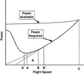
Helicopters are relatively unique in their power requirements in that it takes more power to go slowly. The minimum power required for flight is roughly halfway between minimum speed (i.e. hovering) and maximum speed (Vne). This point is known as Vy and is your best rate of climb speed and conversely, the minimum rate of descent speed for autorotation.
To the left of the graph shows the high power required to remain in the hover, as you increase speed through translational lift the power requirement decreases to its minimum point Vy. Beyond Vy the power requirement for more speed increases up to Vne. This power relationship in helicopters is important to understand during normal and abnormal flight regimes. When making an approach to land from cruise speed, descending while decelerating towards Vy will require more collective input to maintain the required rate of descent as the power differential gap becomes larger. Below Vy, the collective will need to be raised to avoid excessive rates of descent as more power is required to fly slower, all the way back into the hover where the power differential gap is very small and very high power is required.
Gyroscopic Precession/Phase Lag
Control Interaction
Rotary Phenomena
Dissymmetry of Lift
Due to the fact that the lift surfaces of a helicopter are spinning, this creates an unequal amount of lift across the disk which must be accounted for by allowing the blades to move independently in 3 axes separate from blade pitch controlled by the cyclic and collective. The disk needs to be separated into two halves longitudinally, the advancing side and the retreating side. While a helicopter is in forward movement, the advancing blade travelling into the direction of travel will feel greater relative lift than the retreating blade which is experiencing a ‘downwind’ effect. As such having greater lift on one side of the disk than the other would induce a rolling effect similar to that of a plane when adjusting the ailerons.
This ‘dissymmetry of lift’ is countered by the blades moving freely in lead/lag, feathering and flapping. Lead/lag allows the blade to accelerate or decelerate in the same plane of rotation, effectively speeding up and slowing down depending on its location in the advancing/retreating cycle. Feathering is a twisting forced along the span of the blade where the relative pitch angle along the blade becomes varied between the root and tip of the blade. Flapping is the ability of the blade to move freely up and down during the cycle. These forces on the blades work aerodynamically without any input from the pilot but are important to understanding the root causes of dangerous phenomena associated with helicopters.
Retreating Blade Stall
Beyond Vne is where you will encounter RBS due to the excessive aerodynamic forces on the blades. As mentioned in the Dissymmetry of Lift section, the retreating blade is slower relative to the advancing blade and compensates by flapping up and feathering with increased pitch to compesate in order to equalise the lift across the disk. Much like a planes wing, the blade can reach a critical angle and stall. This stall will take place in the 9 o'clock position of the disk in anti-clockwise rotating rotor systems and in the 3 o'clock position in clockwise rotating systems. The effect of which will be a rolling moment to the stalled side, possibly also inducing a violent pitch up (results have been mixed testing in DCS). The rolling moment will increase and will not recover from opposing the roll using cyclic alone.
Recovering from RBS is relatively simple, reduce collective to lower the blade pitch angle and gently pitch up to reduce speed below Vne and until the effects of RBS are no longer apparent. Autorotation can also be used to escape RBS but is not advised in most circumstances.
Vortex Ring State
Vortex Ring State (VRS) is probably the most common destroyer of otherwise perfectly airworthy helicopters being operated by new pilots. As a wing passes through an air mass, the tips generate vortices, unstable swirling air also referred to as wake turbulence. Vortex Ring State is when the tips of the rotor blades are trying to generate lift in their own vortices and can't. The most common flight regime where VRS is encountered is on approach to land. Low airspeed coupled with high rates of descent increase the chances of entering VRS.
- Recognising VRS
- VRS is characterised by uncommanded small yaw movements and a sudden increase in rate of descent with more sluggish cyclic input. As VRS is usually encoutered when attempting to land, the sudden increase in rate of descent while so close to the ground can sometimes mean that recovery is not possible and so understanding contributory factors in VRS and how to avoid them in the first place is paramount.
- Contributory Factors in VRS
- Low airpseed (particularly below translational lift), high rates of descent (>300fpm), high density altitude, high max gross weight, flying downwind, high power applied. If on approach and you recognise any one of these states, take care to consider the dangers of VRS.
- Recovering from VRS
- The most common reaction to seeing a high rate of descent is to apply more collective to arrest the descent, do not under any circumstances apply more power while in vortex ring state. I cannot underline, bold or italic that statement more. Applying more power increases the strength of the vortices and will only increase your rate of descent further. On recognising VRS:
- Lower collective slightly (by half of currently applied) to reduce blade tip vortices
- Pitch forward to increase airspeed and escape the vortices
- Maintain heading using pedals
- Once clear, recover to normal flight
- Another technique is slightly more advanced but recovers from VRS quicker with less height lost and involves flying sideways out of the vortices. Think of it as making a lane change on a highway rather than turning a round a corner.
- Lower collective slightly
- Input lateral cyclic swiftly to enact a fast roll out of the vortices
- Maintain original heading with pedals to create a sideslip rather than a rolling turn
- Once clear, recover to normal flight


