| Line 1: | Line 1: | ||
[[File:F18 DDI test 5.jpeg|526px|center]] | [[File:F18 DDI test 5.jpeg|526px|center]] | ||
{{Columns-list|2| | {{Columns-list|2| | ||
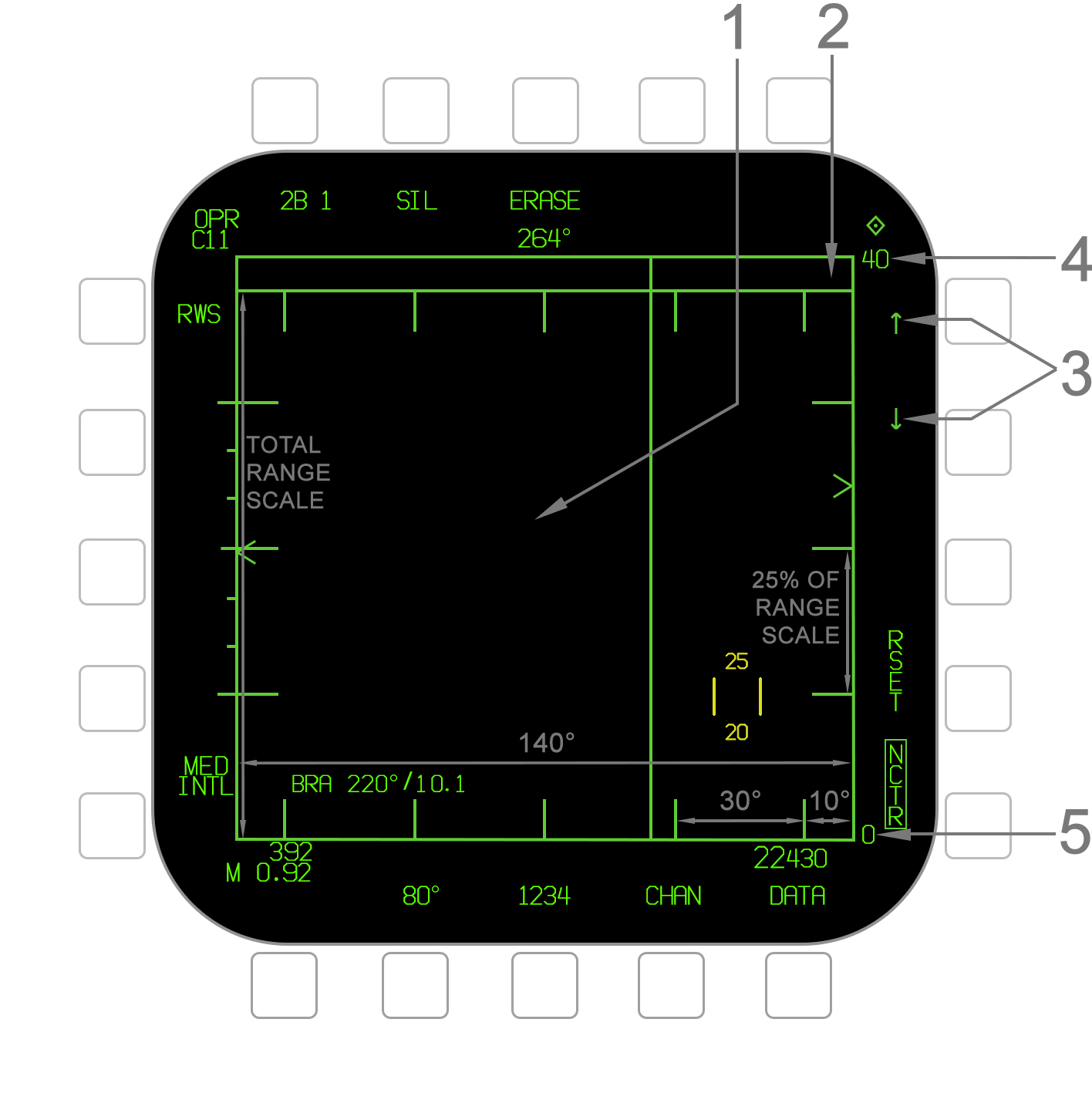
| − | #'''Tactical Region''' - The Attack format provides a top-down view of targets. The area in which they are displayed is termed the "tactical region" which is formed by a green outline around the format. The Attack format covers a 140° region (±70°) which is termed the attack region and spans the Radar gimbal limits. The format is a B-scope projection, meaning that the vector stems on [[#HAFU Symbology|HAFU]] symbols for [[#MSI Trackfiles|MSI trackfiles]] indicate their aspect to ownship as opposed to their absolute direction. Refer to the image below. The tactical region vertically represents a range scale between 5 and 120 miles which is adjustable by the pilot or via the [[#Automatic Range Scale Adjustment (ARSA)|ARSA]] function. Due to the small angle-only trackfile (AOT) zone at the top, the upper 6% of the total range scale is not actually represented. | + | #'''Tactical Region''' - The Attack format provides a top-down view of targets. The area in which they are displayed is termed the "tactical region" which is formed by a green outline around the format. The Attack format covers a 140° region (±70°) which is termed the attack region and spans the Radar gimbal limits. The format is a B-scope projection, meaning that the vector stems on [[#HAFU Symbology|HAFU]] symbols for [[#MSI Trackfiles|MSI trackfiles]] indicate their aspect to ownship as opposed to their absolute direction. Refer to the image below. The tactical region vertically represents a range scale between 5 and 120 miles which is adjustable by the pilot or via the [[#Automatic Range Scale Adjustment (ARSA)|ARSA]] function. Due to the small angle-only trackfile (AOT) zone at the top, the upper 6% of the total range scale is not actually represented. There are scale markings for both azimuth and range, as depicted. Note that the range scale markings change to 20% increments when a 5nm or 10nm scale is selected. |
#'''AOT Zone''' - A separate thin rectanglular area above the main tactical region is termed the angle-only trackfile (AOT) zone or "dugout". This is where [[#Angle Only Trackfiles|angle-only trackfiles]] are displayed for which the Radar has only determined a valid angle and no range. The AOT zone occupies the top 6% of the overall tactical region. | #'''AOT Zone''' - A separate thin rectanglular area above the main tactical region is termed the angle-only trackfile (AOT) zone or "dugout". This is where [[#Angle Only Trackfiles|angle-only trackfiles]] are displayed for which the Radar has only determined a valid angle and no range. The AOT zone occupies the top 6% of the overall tactical region. | ||
#'''Range Scale Arrows''' - These arrows increase and decrease the maximum range scale. The available ranges are 5, 10, 20, 40, 80, and 160nm. Note that when an L&S target is designated, [[#Automatic Range Scale Adjustment (ARSA)|Automatic Range Scale Adjustment]] will occur except when manually overridden. | #'''Range Scale Arrows''' - These arrows increase and decrease the maximum range scale. The available ranges are 5, 10, 20, 40, 80, and 160nm. Note that when an L&S target is designated, [[#Automatic Range Scale Adjustment (ARSA)|Automatic Range Scale Adjustment]] will occur except when manually overridden. | ||
Revision as of 10:32, 26 April 2021
- Tactical Region - The Attack format provides a top-down view of targets. The area in which they are displayed is termed the "tactical region" which is formed by a green outline around the format. The Attack format covers a 140° region (±70°) which is termed the attack region and spans the Radar gimbal limits. The format is a B-scope projection, meaning that the vector stems on HAFU symbols for MSI trackfiles indicate their aspect to ownship as opposed to their absolute direction. Refer to the image below. The tactical region vertically represents a range scale between 5 and 120 miles which is adjustable by the pilot or via the ARSA function. Due to the small angle-only trackfile (AOT) zone at the top, the upper 6% of the total range scale is not actually represented. There are scale markings for both azimuth and range, as depicted. Note that the range scale markings change to 20% increments when a 5nm or 10nm scale is selected.
- AOT Zone - A separate thin rectanglular area above the main tactical region is termed the angle-only trackfile (AOT) zone or "dugout". This is where angle-only trackfiles are displayed for which the Radar has only determined a valid angle and no range. The AOT zone occupies the top 6% of the overall tactical region.
- Range Scale Arrows - These arrows increase and decrease the maximum range scale. The available ranges are 5, 10, 20, 40, 80, and 160nm. Note that when an L&S target is designated, Automatic Range Scale Adjustment will occur except when manually overridden.
- Maximum Range Scale - This value indicates the maximum range from ownship currently being displayed by the tactical region as set by the range scale arrows, except in certain cases like Expanded (EXP) mode or SCAN RAID. Note that the last 6% of the maximum range scale is not actually displayed due to the AOT zone taking up the top 6% of the tactical region. For example, if the maximum range scale is 20nm, the maximum range is actually 18.8nm (94% of 20).
- Minimum Range Scale - This value indicates the minimum range from ownship currently being displayed by the tactical region. This is almost always 0nm (i.e. ownship is at the bottom of the format), except when in the Expanded (EXP) TWS format or SCAN RAID/RAID modes.

